Quantcast
Channel: EEP – Electrical Engineering Portal
Viewing all 1475 articles
Browse latest View live

Inspection and Test Procedures for LV Cables

$
0
0
Inspection and Test Procedures for LV Cables

Inspection and Test Procedures for LV Cables

Content

  1. Visual and Mechanical Inspection
  2. Electrical Tests
  3. Test Values
  4. TABLE 100.12 – US Standard Fasteners – Bolt-Torque Values for Electrical Connections

Cables, Low-Voltage, 600 Volt Maximum

1. Visual and Mechanical Inspection

  1. Compare cable data with drawings and specifications.
  2. Inspect exposed sections of cables for physical damage and correct connection in accordance with single-line diagram.
  3. Inspect bolted electrical connections for high resistance using one of the following methods:
    1. Use of low-resistance ohmmeter in accordance with previous Section 1.2.
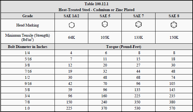
    2. Verify tightness of accessible bolted electrical connections by calibrated torque-wrench method in accordance with manufacturer’s published data or Table 100.12.
    3. Perform thermographic survey:
    • Perform thermographic survey when load is applied to the system
    • Remove all necessary covers prior to thermographic inspection. Use appropriate caution, safety devices, and personal protective equipment
    • Perform a follow-up thermographic survey within 12 months of final acceptance by the owner
  4. Inspect compression-applied connectors for correct cable match and indentation.
  5. Inspect for correct identification and arrangements.
  6. Inspect jacket insulation and condition.
  7. Go to Content ↑


    2. Electrical Tests

    1. Perform resistance measurements through bolted connections with low-resistance ohmmeter.
    2. Perform insulation-resistance test on each conductor with respect to ground and adjacent conductors. Applied potential shall be 500 volts DC for 300 volt rated cable and 1000 volts DC for 600 volt rated cable. Test duration shall be one minute.
    3. Perform continuity tests to insure correct cable connection.
    4. Verify uniform resistance of parallel conductors.

    Go to Content ↑


    3. Test Values

    1. Compare bolted connection resistances to values of similar connections.
    2. Bolt-torque levels should be in accordance with Table 100.12 unless otherwise specified by the manufacturer.
    3. Microhm or millivolt drop values shall not exceed the high levels of the normal range as indicated in the manufacturer’s published data. If manufacturer’s datais not available, investigate any values which deviate from similar connections by more than 50 percent of the lowest value.
    4. Insulation-resistance values should not be less than 50 megohms.
    5. Investigate deviations in resistance between parallel conductors.

    Go to Content ↑

    TABLE 100.12

    US Standard Fasteners – Bolt-Torque Values for Electrical Connections

    Table 100.12.1 - Heat-Treated Steel - Cadmium or Zinc Plated

    Table 100.12.1 - Heat-Treated Steel - Cadmium or Zinc Plated


    Table 100.12.2 - Silicon Bronze Fasteners

    Table 100.12.2 - Silicon Bronze Fasteners


    Table 100.12.3 - Aluminum Alloy Fasteners

    Table 100.12.3 - Aluminum Alloy Fasteners


    Table 100.12.4 - Stainless Steel Fasteners

    Table 100.12.4 - Stainless Steel Fasteners


    a. Consult manufacturer for equipment supplied with metric fasteners.
    b. This table is based on bronze alloy bolts having a minimum tensile strength of 70,000 pounds per square inch.
    c. This table is based on aluminum alloy bolts having a minimum tensile strength of 55,000 pounds per square inch.
    d. This table is to be used for the following hardware types:

    • Bolts, cap screws, nuts, flat washers, locknuts (18–8 alloy)
    • Belleville washers (302 alloy).

    Go to Content ↑

    Resource: Acceptance Testing Specifications for Electrical Power Distribution Equipment and Systems – NETA 2003


    How to Predict Life Span of the Switchgear?

    $
    0
    0
    How to Predict Life Span of the Switchgear?

    How to Predict Life Span of the Switchgear? (photo by Milos Diskovic)

    Load and Number of Switching Cycles

    The life span of switchgear basically depends on the size of the load and the number of switching cycles. Instead of a time span, with electromechanical switchgear reference is usually made to the number of operations, as the ageing mainly depends on the stress during switching and less on the on- and off-phases between.

    The maximum number of operations is determined by the wear of heavily loaded components in:

    1. Contactors,
    2. Load switches and
    3. Circuit breakers especially of the contact system.

    For switchgear, the mechanical and electrical life spans are separately defined. The mechanical life span states the number of possible operations without electrical loading, while the electrical life span states the number of operations for a certain size of electrical loading and a certain utilization category.

    In electronic devices, the life span is usually less dependent on the number of operations but rather on the working temperature. Thus for example electrolytic capacitors (for example used in power adapters) age more quickly at higher temperatures.

    This is why it is recommended to install electronic devices in the cooler parts of switch cabinets.

    Ageing is also a problem with fuses, especially in the context of switching of motors.

    Full-range fuses (gL, gG) have a soldered joint for tripping in the overcurrent range that may age due for example to repeated short-term melting. When using them with motors with the latters’ high starting currents, it should therefore be ensured that the starting current does not raise the temperature of this solder joint beyond a certain limit.

    Fuse manufacturers provide information on the smallest fuses that can be selected in relation to given motor currents and starting times.


    Prospective Service Life

    The prospective service life of switchgear is the number of years, months or weeks that it should complete under the foreseen service conditions in 1-, 2- or 3-shift operation without the replacement of spare parts. It depends on the frequency of operation and the total number of individual switching operations.

    For the latter in addition to the mechanical also the electrical life span of the devices must be selected accordingly.

    The required parameters can be determined by means of the below formulae:

    ntot = fs x hD x dx nY

    nY = ntot / ( fs x hD x dY )

    fs = ntot / ( nY x hD x dY )

    ntot – Total number of operations (life span)
    fs – Switching operations per hour
    hD – Operating hours per day
    dY – Operating days per year
    nY – Number of years (life span)


    Mechanical Life Span

    The mechanical life span of switchgear is the total number of possible switch operations without electrical switch loading. It depends on the design, the masses moved, the forces and accelerations occurring.

    Large load switches and circuit breakers operate with high contact forces and large masses, and therefore have a comparatively short mechanical life span.

    On the other hand, contactors operate with relatively small contact forces and thus achieve longer mechanical life spans.

    After the mechanical life span has expired, the devices must be replaced. This life span is only rarely achieved during the foreseen service life. In a few cases, where the complete mechanical life span has to be used, it should be ensured that it is not reduced by adverse ambient conditions, installation position and – in the case contactors – by an excessive control voltage.


    Electrical Life Span

    The electrical life span for switchgear is the number of possible switching operations under operational conditions. After this number has been reached, the parts subject to wear must be wherever possible replaced. With small devices, the entire device must be replaced.

    Depending on the application, the loading and the resulting erosion of the contacts varies widely.

    This is influenced by the following conditions, whereby the first mentioned play the dominant role:

    1. Breaking current
    2. Making current
    3. Voltage
    4. Power factor cos φ with alternating current
    5. Time constant τ with direct current
    6. Frequency of operation
    7. Malfunctions in the plant and on other devices (contact chatter)
    8. Ambient conditions (climate, temperature, vibrations)

    Usually the electrical life span determined under test conditions is presented in diagrams as a function of the rated operational current. These values may generally be used without hesitation in contactor selection. In practical operation, the loads are usually lower, as the running motor usually carries a current that is below the rated operational current. In the case of longer inching operation, the starting current has already dropped somewhat by the time the motor is switched off.

    This usually compensates for the effect of any disregarded adverse conditions.

    For the most common applications of contactors the electrical life span is presented in the product documentation with various diagrams:

    • AC-1 Non-inductive or slightly inductive loads, for example resistance furnaces
      (small making current and cos φ higher than with AC-3, however full recurring voltage on switching off)
    • AC-3 Squirrel-cage induction motors: Starting, switching off motors during running
      (high making current, breaking of the motor rated current)
    • AC-2 Slip-ring motors: Starting, switching off
    • AC-4 Squirrel-cage motors: Starting, plugging, inching (high making and breaking current at full voltage)
    • Mixed service of slip-ring motors, e.g.
      - AC-3 90 %
      - AC-4 10 %

    With the curves Figure 1 for AC-3 and Figure 2 for AC-4 the expected electrical life span for specific applications can be determined.

    These curves also can be used to determine the electrical life span for any application (for example jogging motors with very high or especially low starting current and any mixed service).

    Example of a diagram for determining the electrical life span of contactors

    Figure 1 - Example of a diagram for determining the electrical life span of contactors as a function of the rated operational current Ie for utilization category AC-3


    The diagram applies up to 460 V, 50/60 Hz.


    Example 1

    Background:
    Squirrel-cage induction motor 7.5 kW, 400 V, 15.5 A, AC-3 (switching off only when running), operating cycle 2 minutes ON / 2 minutes OFF, 3-shift operation, expected service life 8 years.

    Objective:
    Selection of the contactor

    Solution:
    2 min ON + 2 min OFF = 15 switching operations/h. This results for 3-shift operation over 8 years in around 1 million switching operations.

    From diagram Figure 1 yields for a rated operational current of 15.5 A and 1 million required switching operations the contactor C16 (electrical life span approx. 1.3 million switching operations).

    Example of a diagram for determining the electrical life span of contactors

    Figure 2 - Example of a diagram for determining the electrical life span of contactors as a function of the rated operational current Ie for utilization category AC-4


    The diagram applies up to Ue=690 V, 50/60 Hz.


    Example 2

    Background:
    Squirrel-cage induction motor 15 kW, 400 V, 29 A, plugging, switching off rotor at standstill at IA = 6·Ie, expected life span = 0.2 million switching operations.

    Objective:
    Rating of starting and braking contactors.

    Solution:
    The starting contactor (circuit making only) is selected according to the maximum permitted rated power at AC-3 (see Figure 1): C30.

    The brake contactor is selected according to the maximum permitted rated operational power at AC-4 and 0.2 million switching operations according to Diagram Figure 2 –  C72.

    For mixed service, i.e. service of the contactor with AC-3 and AC-4 switching operations, the life span results from the sum of the loadings. In the catalogs, diagrams for certain %-rates of AC-4 operations, for example 10 %, are provided. The RALVET electronic documentation is available for determining the life span for other percentage rates, or direct inquires must be made.

    If in practice the electrical life span was considerably shorter than desired, there are several possible causes and explanations:
    • More switching operations than expected, e.g. operated by extremely sensitive controller.
    • More frequent inching than expected, e.g. unskilled operation.
    • Permitted frequency of operation exceeded, e.g. chattering contacts
    • Short-circuits, e.g. switching pause too short for reversing or star-delta starters.
    • Synchronization with the supply voltage. Semiconductors as controllers could for example always switch off at the same phase angle and act in the same direction of current-flow
      (results in one-sided material migration to the contacts like in direct current control).

    Assessment of the Contacts

    In conjunction with the electrical life span, the question often arises of assessment of contacts after a certain service period for continued serviceability. At least with large contactors, the contacts can be inspected.

    Already after the first few switching operations, there are clear signs of burn-off on the contact surface. After a relatively small number of switching operations, the entire contact surface becomes roughened and blackened. Black deposits and traces of arc extinction can be seen on the surrounding components. Serrated edges and loss of contact material toward the arcing chamber are also normal.

    The end of the contact life span is really reached when larger areas of the contact plating have broken off or there is a danger of the contact touching the substrate material.

    The below figures are intended as an aid for an assessment of contacts.

    Contacts of a power contactor at various stages of the life span with AC-3 loading

    Figure 3 - Contacts of a power contactor at various stages of the life span with AC-3 loading


    Figure 3 left – Contacts in new state
    Figure 3 center – Contacts after approx. 75 % of the electrical life span; Contact material partially eroded; contacts still operable
    Figure 3 right – Contacts at the end of their life span; Substrate material visible, contact material eroded down to the substrate; further use would lead to contact welding and excessive temperature rise.

    The pictures on the right show the contact state in long section. The images of the various life span phases originate from various contacts, as the contacts can no longer be used once the section has been cut.

    Resource: Allen Bradley – Low Voltage Switchgear and Controlgear

    The Purpose Of Transformer Gas Relay

    $
    0
    0
    The Purpose Of Transformer Gas Relay

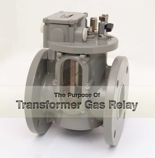
    The Purpose Of Transformer Gas Relay (on photo: Gas actuated relay for oil-filled transformers by Cedaspe S.p.a.)

    Introduction

    The transformer gas relay is a protective device installed on the top of oil-filled transformers. It performs two functions. It detects the slow accumulation of gases, providing an alarm after a given amount of gas has been collected.

    Also, it responds to a sudden pressure change that accompanies a high rate of gas production (from a major internal fault), promptly initiating disconnection of the transformer.

    An incipient fault or developing fault, usually causes slow formation of gas.

    Examples of incipient faults are:

    • Current flow through defective supporting and insulating structures;
    • Defective joints at winding terminals causing heating;
    • Minor tap changer troubles; and
    • Core faults.

    A major fault is one that results in a fast formation of a large volume of gases. Examples of such faults are:
    • Shorts between turns and windings; and
    • Open circuits, which result in severe arcing.

    Failure to disconnect the transformer under fault conditions can result in severe equipment damage from high gas and oil pressures and the effect of the electrical fault.

    Generation of Gas Due to Faults

    Internal transformer electrical faults result in the production of ionized gases. A significant volume of gas is frequently generated in the early stages of a fault by rapid oil breakdown.

    The generated gases rise through the oil to the top of the equipment and collect in the gas relay.

    Once a sufficient volume of gas has accumulated, an alarm is generated by contacts within the gas relay.

    In the event of a gas alarm, it is necessary to sample and analyze the gas being generated. This analysis, together with knowledge of the rate at which gas is accumulating, will determine the proper course of action. If a fault is thought to be developing, the device must be removed from service.

    Ignoring this early warning sign can lead to severe equipment damage as the fault progresses.


    Operation of a Transformer Gas Relay

    A typical transformer gas relay consists of two chambers, each performing a distinctive function. A simplified cross-section of a gas relay is shown in Figure 1.

    The relay assembly consists of a gas accumulation chamber mounted directly over a pressure chamber. The accumulation chamber collects slowly produced gases. A float located in this partially oil-filled chamber moves as the gas volume increases. It operates an alarm switch when the amount of gas collected reaches a specified level.

    An indicator coupled to the float also provides a means to monitor the rate at which gas is being generated.

    Typical Transformer Gas Relay

    Figure 1 - Typical Transformer Gas Relay


    The second chamber, a pressure chamber, connects directly to the transformer oil circuit. It connects vertically to the accumulation chamber, providing a path for the rising gas.

    An air-filled bellows within the pressure chamber acts as the pressure change detector. A sudden pressure surge in the oil compresses the bellows and forces the
    air within to move a diaphragm. The moving diaphragm actuates a switch that initiates tripping of the transformer.

    Sudden pressures, such as oil circulating pump surges, are normal operating events and the relay must be set to ride through them. In practice, it is necessary to make sure the relay is set to operate at about 7 KPa (1 psi) above the maximum oil circulating pump surge pressure.

    Dangerously high pressure increases from major faults are relieved by an explosion vent on the top of the transformer tank.

    This is basically a diaphragm sealed pipe with its open end directed away from the transformer.

    A significant increase in pressure bursts the diaphragm and discharges gases and hot oil with a possibility of resulting fire.


    Buchholz Relay (VIDEO)

    Cant see this video? Click here to watch it on Youtube.

    Resource: Science and Reactor Fundamentals – Electrical; CNSC Technical Training Group

    Arrangements of LV Utility Distribution Networks (1)

    $
    0
    0
    Arrangements of LV Utility Distribution Networks

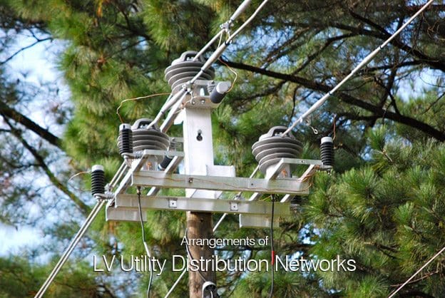
    Arrangements of LV Utility Distribution Networks (photo credit to abbmvit.blogspot.com)

    Introduction

    In European countries the standard 3-phase 4-wire distribution voltage level is 230/400 V. Many countries are currently converting their LV systems to the latest IEC standard of 230/400 V nominal (IEC 60038).

    Medium to large-sized towns and cities have underground cable distribution systems.

    MV/LV distribution substations, mutually spaced at approximately 500-600 metres, are typically equipped with:

    1. A 3-or 4-way MV switchboard, often made up of incoming and outgoing load-break switches forming part of a ring main, and one or two MV circuit-breakers or combined fuse/ load-break switches for the transformer circuits
    2. One or two 1,000 kVA MV/LV transformers
    3. One or two (coupled) 6-or 8-way LV 3-phase 4-wire distribution fuse boards, or moulded-case circuit-breaker boards, control and protect outgoing 4-core distribution cables, generally referred to as “distributors

    The output from a transformer is connected to the LV busbars via a load-break switch, or simply through isolating links. In densely-loaded areas, a standard size of distributor is laid to form a network, with (generally) one cable along each pavement and 4-way link boxes located in manholes at street corners, where two cables cross.

    Recent trends are towards weather-proof cabinets above ground level, either against a wall, or where possible, flush-mounted in the wall. Links are inserted in such a way that distributors form radial circuits from the substation with open-ended branches (see Fig. C3).

    Where a link box unites a distributor from one substation with that from a neighbouring substation, the phase links are omitted or replaced by fuses, but the neutral link remains in place.

    Showing one of several ways in which a LV distribution network may be arranged

    Fig. C3 : Showing one of several ways in which a LV distribution network may be arranged for radial branched-distributor operation, by removing (phase) links


    This arrangement provides a very flexible system in which a complete substation can be taken out of service, while the area normally supplied from it is fed from link boxes of the surrounding substations.

    Moreover, short lengths of distributor (between two link boxes) can be isolated for fault-location and repair. Where the load density requires it, the substations are more closely spaced, and transformers up to 1,500 kVA are sometimes necessary.

    Other forms of urban LV network, based on free-standing LV distribution pillars, placed above ground at strategic points in the network, are widely used in areas of lower load density. This scheme exploits the principle of tapered radial distributors in which the distribution cable conductor size is reduced as the number of consumers downstream diminish with distance from the substation.

    In this scheme a number of large-sectioned LV radial feeders from the distribution board in the substation supply the busbars of a distribution pillar, from which smaller distributors supply consumers immediately surrounding the pillar.

    Distribution in market towns, villages and rural areas generally has, for many years, been based on bare copper conductors supported on wooden, concrete or steel poles, and supplied from pole-mounted or ground-mounted transformers.

    In recent years, LV insulated conductors, twisted to form a two-core or 4-core self supporting cable for overhead use, have been developed, and are considered to be safer and visually more acceptable than bare copper lines. This is particularly so when the conductors are fixed to walls (e.g. under-eaves wiring) where they are hardly noticeable.

    Improved methods using insulated twisted conductors to form a pole mounted aerial cable are now standard practice in many countriesAs a matter of interest, similar principles have been applied at higher voltages, and self supporting “bundled” insulated conductors for MV overhead installations are now available for operation at 24 kV. Where more than one substation supplies a village, arrangements are made at poles on which the LV lines from different substations meet, to interconnect corresponding phases.

    North and Central American practice differs fundamentally from that in Europe, in that LV networks are practically nonexistent, and 3-phase supplies to premises in residential areas are rare.

    The distribution is effectively carried out at medium voltage in a way, which again differs from standard European practices.

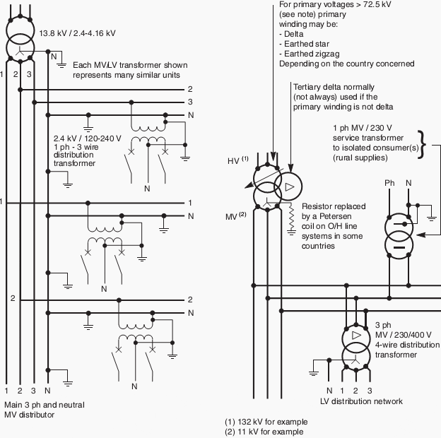
    The MV system is, in fact, a 3-phase 4-wire system from which single-phase distribution networks (phase and neutral conductors) supply numerous single-phase transformers, the secondary windings of which are centre-tapped to produce 120/240 V single-phase 3-wire supplies.

    In Europe, each utility-supply distribution substation is able to supply at LV an area corresponding to a radius of approximately 300 metres from the substation. North and Central American systems of distribution consist of a MV network from which numerous (small) MV/LV transformers each supply one or several consumers, by direct service cable (or line) from the transformer location

    The central conductors provide the LV neutrals, which, together with the MV neutral conductors, are solidly earthed at intervals along their lengths. Each MV/LV transformer normally supplies one or several premises directly from the transformer position by radial service cable(s) or by overhead line(s).

    Many other systems exist in these countries, but the one described appears to be the most common. Figure C4 (in next part…) shows the main features of the two systems.

    Will be continued…

    Resource: Electrical Installation Guide 2009 – Schneider Electric

    Arrangements of LV Utility Distribution Networks (2)

    $
    0
    0
    Arrangements of LV Utility Distribution Networks

    Arrangements of LV Utility Distribution Networks (photo by Steve Ives @ Flickr: Street in Haddington, Philadelphia, PA, US)


    Continued from the previous part: Arrangements of LV Utility Distribution Networks (1)


    The consumer-service connection

    In the past, an underground cable service or the wall-mounted insulated conductors from an overhead line service, invariably terminated inside the consumer’s premises, where the cable-end sealing box, the utility fuses (inaccessible to the consumer) and meters were installed.

    A more recent trend is (as far as possible) to locate these service components in a weatherproof housing outside the building.

    Widely-used American and European-type systems

    Fig. C4: Widely-used American and European-type systems


    Note: At primary voltages greater than 72.5 kV in bulk-supply substations, it is common practice in some European countries to use an earthed-star primary winding and a delta secondary winding. The neutral point on the secondaryside is then provided by a zigzag earthing reactor,the star point of which is connected to earth through a resistor. 

    Frequently, the earthing reactor has a secondary winding to provide LV3-phase supplies for the substation. It is then referred to as an “earthing transformer”.

    A MCCB  - moulded case circuit breaker which incorporates a sensitive residual-current earth-fault protective feature is mandatory at the origin of any LV installation forming part of a TT earthing system.

    The utility/consumer interface is often at the outgoing terminals of the meter(s) or, in some cases, at the outgoing terminals of the installation main circuit-breaker (depending on local practices) to which connection is made by utility staff, following a satisfactory test and inspection of the installation.

    A typical arrangement is shown in Figure C5.

    Typical service arrangement for TT-earthed systems

    Fig. C5: Typical service arrangement for TT-earthed systems


    A further reason for this MCCB is that the consumer cannot exceed his (contractualdeclared maximum load, since the overload trip setting, which is sealed by the supply authority, will cut off supply above the declared value. Closing and tripping of the MCCB is freely available to the consumer, so that if the MCCB is inadvertently tripped on overload, or due to an appliance fault, supplies can be quickly restored following correction of the anomaly.

    In view of the inconvenience to both the meter reader and consumer, the location of meters is nowadays generally outside the premises, either:

    • In a free-standing pillar-type housing as shown in Figures C6 and C7
    • In a space inside a building, but with cable termination and supply authority’s fuses located in a flush-mounted weatherproof cabinet accessible from the public way, as shown in Figure C8
    • For private residential consumers, the equipment shown in the cabinet in.
    Typical rural-type installation

    Fig. C6 : Typical rural-type installation


    In this kind of installation it is often necessary to place the main installation circuit-breaker some distance from the point of utilization, e.g. saw-mills, pumping stations,  etc.


    Semi-urban installations (shopping precincts, etc.)

    Fig. C7: Semi-urban installations (shopping precincts, etc.)


    The main installation CB is located in the consumer’s premises in cases where it is  set to trip if the declared kVA load demand is exceeded.


    Town centre installations

    Fig. C8: Town centre installations


    The service cable terminates in a flushmounted wall cabinet which contains the  isolating fuse links, accessible from the public way. This method is preferred for  esthetic reasons, when the consumer can provide a suitable metering and main-switch location.


    Typical LV service arrangement for residential consumers

    Fig. C9: Typical LV service arrangement for residential consumers


    Figure C5 is installed in a weatherproof cabinet mounted vertically on a metal frame in the front garden, or flush mounted in the boundary wall, and accessible to authorized personnel from the pavement.

    Figure C9 shows the general arrangement, in which removable fuse links provide the means of isolation.

    In the field of electronic metering, techniques have developed which make their use attractive by utilities either for electricity metering and for billing purposes, the liberalisation of the electricity market having increased the needs for more data collection to be returned from the meters.

    For example electronic metering can also help utilities to understand their customers’ consumption profiles.

    In the same way, they will be useful for more and more power line communication and radio-frequency applications as well.

    In this area, prepayment systems are also more and more employed when economically justified. They are based on the fact that for instance consumers having made their payment at vending stations, generate tokens to pass the information concerning this payment on to the meters. For these systems the key issues are security and inter-operability which seem to have been addressed successfully now.

    The attractiveness of these systems is due to the fact they not only replace the meters but also the billing systems, the reading of meters and the administration of the revenue collection.

    Resource: Electrical Installation Guide 2009 – Schneider Electric

    Definition of Basic Insulation Level (BIL)

    $
    0
    0
    Definition of Basic Insulation Level (BIL)

    Definition of Basic Insulation Level (BIL) - photo by bob1217 @ Flickr

    Introduction to BIL

    Insulation levels are designed to withstand surge voltages, rather than only normal operating voltages. Since the insulation lines and equipment is protected by surge arresters draining the surges rapidly before the insulation is damaged, the arrester must operate below the minimum insulation level that must withstand the surges.

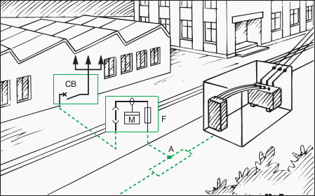
    An example is shown in Figure 1a below.

    The minimum level is known as the Basic Insulation Level (BIL) that must be that of all of the components of a system.

    Insulation coordination

    Figure 1a - Insulation coordination


    Insulation values above this level for the lines and equipment in the system must be so coordinated that specific protective devices operate satisfactorily below that minimum level.

    In the design of lines and equipment considering the minimum level of insulation required, it is necessary to define surge voltage in terms of its peak value and return to lower values in terms of time or duration. Although the peak voltage may be considerably higher than normal voltage, the stress in the insulation may exist for only a very short period of time.

    For purposes of design, the voltage surge is defined as one that peaks in 1.5 microseconds and falls to one-half that value in 40 microseconds (thousandths of a second).

    It is referred to as a 1.5/40 wave, the steep rising portion is called the wave front and the receding portion the wave tail, Figure 2.

    Surge Voltage 1.5 by 4.0 Wave

    Figure 2 - Surge Voltage 1.5 by 4.0 Wave

    Insulation levels recommended for a number of voltage classes are listed in Table 1. As the operating voltages become higher, the effect of a surge voltage becomes less; hence, the ratio of the BIL to the voltage class decreases as the latter increases.

    Table 1 – Typical Basic Insulation Levels

    Basic insulation level, kV
    (standard 1.5- × 40-μs wave)
    Voltage class, kVDistribution classPower class (station, transmission lines)
    1.23045
    2.54560
    5.06075
    8.77595
    1595110
    23110150
    34.5150200
    46200250
    69250350

    *For current industry recommended values, refer to the latest revision of the National Electric Safety Code.

    Distribution class BIL is less than that for power class substation and transmission lines as well as consumers’ equipment, so that should a surge result in failure, it will be on the utility’s distribution system where interruptions to consumers are limited and the utility better equipped to handle such failures.

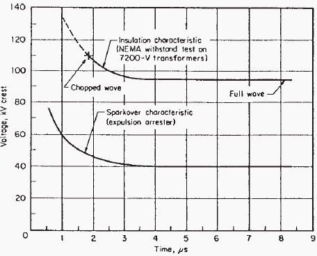
    The line and equipment insulation characteristics must be at a higher voltage level than that at which the protecting arrester begins to spark over to ground, and a sufficient voltage difference between the two must exist.

    The characteristics of the several type arresters are shown in the curves of Figure 3.

    Sparkover Characteristics of Distribution Value / Expulsion Arresters

    Figure 3 - (a) Sparkover Characteristics of Distribution Value Arresters; (b) Sparkover Characteristics of Expulsion Arresters


    The impulse level of lines and equipment must be high enough for the arresters to provide protection but low enough to be economically practical.

    Surges, on occasion, may damage the insulation of the protective device; hence, insulation coordination should include that of the protective devices.

    As there are a number of protective devices, mentioned earlier, each having characteristics of its own, the characteristics of all of these must be coordinated for proper operation and protection.

    Before leaving the subject of insulation coordination, such coordination also applies within a piece of equipment itself. The insulation associated with the several parts of the equipment must not only withstand the normal operating voltage, but also the higher surge voltage that may find its way into the equipment.

    So, while the insulation of the several parts is kept nearly equal, that of certain parts is deliberately made lower than others; usually this means the bushing. Since the bushing is usually protected by an air gap or arrester whose insulation under surge is lower than its own, flashover will occur across the bushing and the grounded tank.

    The weakest insulation should be weaker by a sufficient margin than that of the principal equipment it is protecting; such coordinated arrangement restricts damage not only to the main parts of the equipment, but less so to parts more easily accessible for repair or replacement.

    The insulation of all parts of the equipment should exceed the basic insulation level (BIL). Figure 1b.

    Simplistic diagram illustrating Basic insulation level (BIL) and Insulation coordination

    Figure 1b - Simplistic diagram illustrating Basic insulation level (BIL) and Insulation coordination


    Resource: Power Transmission and Distribution – Anthony J. Pansini (Get this book from Amazon)

    Classes, Speed Control and Starting of DC motors

    $
    0
    0
    Classes, Speed Control and Starting of DC motors

    Classes, Speed Control and Starting of DC motors (on photo: Sugarcane Mill Rolling DC Motor; 440/220VDC; 500kW; with Shunt-wound construction)

    DC Motor Classes

    D.C. motors are divided into three classes, as follows:

    1. The series-wound motor

    In this type (Figure 1) the field is in series with the armature. This type of DC motor is only used for direct coupling and other work where the load (or part of the load) is permanently coupled to the motor. This will be seen from the speed-torque characteristic, which shows that on no load or light load the speed will be very high and therefore dangerous.

    Series-wound motor

    Figure 1 - Series-wound motor

    2. The shunt-wound motor

    In this case the field is in parallel with the armature, as shown in Figure 2, and the shunt motor is the standard type of d.c. motor for ordinary purposes.

    Its speed is nearly constant, falling off as the load increases due to resistance drop and armature reaction.

    Shunt-wound motor

    Figure 2 - Shunt-wound motor

    3. The compound-wound motor

    This is a combination of the above two types. There is a field winding in series with the armature and a field winding in parallel with it (Figure 3). The relative proportions of the shunt and series winding can be varied in order to make the characteristics nearer those of the series motor or those of the shunt-wound motor.

    The typical speed-torque curve is shown in the diagram.

    Compound-wound motors are used for cranes and other heavy duty applications where an overload may have to be carried and a heavy starting torque is required.

    Compound-wound motor

    Figure 3 - Compound-wound motor

    Speed control

    Speed control is obtained as follows:

    For series motors

    By series resistance in parallel with the field winding of the motor. The resistance is then known as a diverter resistance.

    Another method used in traction consists of starting up two motors in series and then connecting them in parallel when a certain speed has been reached. Series resistances are used to limit the current in this case.


    For shunt and compound-wound motors

    Speed regulation on shunt and compound-wound motors is obtained by resistance in series with the shunt-field winding only. This is shown diagrammatically for a shunt motor in Figure 4.

    Left: Diagram of faceplate starter for shunt motor; Ritght: Speed control of shunt motor by field rheostat

    Figure 4 - Left: Diagram of faceplate starter for shunt motor; Ritght: Speed control of shunt motor by field rheostat

    Starting

    The principle of starting a shunt motor will be seen from Figure 4 which shows the faceplate-type starter, the starting resistance being in between the segments marked 1, 2, 3, etc. The starting handle is held in position by the no-volt coil, marked NV, which automatically allows the starter to return to the off position if the supply fails.

    Overload protection is obtained by means of the overload coil, marked OL, which on overload short-circuits the no-volt coil by means of the contacts marked a and b.

    When starting a shunt-wound motor it is most important to see that the shunt rheostat (for speed control) is in the slow-speed position. This is because the starting torque is proportional to the field current and this field current must be at its maximum value for starting purposes.

    Many starters have the speed regulator interlocked with the starting handle so that the motor cannot be started with a weak field.

    These methods of starting are not used much today but are left in because many installations still exist. Modern methods of control employ static devices described below.


    Ward-Leonard control

    One of the most important methods of speed control is that involving the Ward-Leonard principle which comprises a d.c. motor fed from its own motor generator set.

    The diagram of connections is shown in Figure 5.

    The usual components are an a.c. induction or synchronous motor, driving a d.c. generator, and a constant voltage exciter; a shunt-wound d.c. driving motor and a field rheostat. The speed of the driving motor is controlled by varying the voltage applied to the armature, by means of the rheostat in the shunt winding circuit of the generator.

    The d.c. supply to the field windings of the generator and driving motor is obtained by means of an exciter driven from the generator shaft.

    Ward-Leonard control

    Figure 5 - Ward-Leonard control


    With the equipment it is possible to obtain 10 to 1 speed range by regulation of the generator shunt field and these sets have been used for outputs of 360W and upwards. On the smaller sizes speed ranges up to 15 to 1 have been obtained, but for general purposes the safe limit can be taken as 10 to 1.

    Speed control obtained in this way is extremely stable and the speed regulation between no load and full load at any particular setting is from 7 to 10%, depending on the size and design of the equipment.

    This type of drive has been used for a variety of industrial applications and has been particularly successful in the case of electric planers and certain types of lifts, with outputs varying from 15 kW to 112 kW, also in the case of grinders in outputs of 360 W, 3/4kW and 11/2kW with speed ranges from 6 : 1 to 10 : 1.


    Thyristor regulators

    The development of thyristors with high current carrying capacity and reliability has enabled thyristor regulators to be designed to provide a d.c. variable drive system that can match and even better the many a.c. variable-speed drive systems on the market.

    This has meant a redesign of the d.c. motor to cater for the characteristics of the thyristor regulator.

    Machines have laminated poles and smaller machines may also have laminated yokes. This is to improve commutation by allowing the magnetic circuit to respond more quickly to flux changes caused by the thyristor regulators. Square frame designs of d.c. machines have also been developed with much improved power/weight ratios together with other advantages.

    Resource: Newnes Electrical Pocket Book – E.A. Reeves, Martin J. Heathcote (Get this book from Amazon)

    How Power Transformer Produces Acoustical Noise?

    $
    0
    0
    How power transformer produces acoustical noise?

    How power transformer produces acoustical noise? (on photo dry type transformer by Megawatt)

    Why does a transformer make noise?

    This technical article explains the acoustic noise generating mechanism inside power transformers.

    Transformer noise has two sources: winding vibrations and core vibrations. The single most effective way to reduce windings noise is by having a good quality controlled winding process when assembling them. This article focusses on the cores of normally silent transformers, which make noise under adverse mains conditions.

    Transformer cores can become noisy as well under specific secondary load conditions which can be translated (transformed) into the adverse mains conditions at the primary as discussed in this article.

    There are three physical phenomena that produce noise in the magnetic core:

    1. The movement of the 90-degree Bloch walls inside the magnetic domains, frequently called Magnetoacoustic Emission (MAE) (see Figure 1)
    2. The rotation of the magnetic domains, that is responsible for the bulk magnetostriction (see Figure 2)
    3. The Lorentz Force Acoustic Signal (LFAS) causing mechanical forces between laminations of the core (see Figure 3)

    MAE occurs in the steep section of the hysteresis loop; see Figure 4. Not much sound is emitted and the bulk magnetostriction is small. The rotation of the magnetic domains is dominant near saturation in the hysteresis loop.

    The magnetostriction becomes “large” and the core laminations move considerably, thus generating acoustic noise (see Figure 4).

    The rattling of laminations of the core (LFAS) depends largely on the construction of the core. The EI-type cores are more prone to make noise due to their many separated pieces of lamination which mostly are only sturdy clamped at the four corners. In toroidal cores the long role of core band is sturdy clamped everywhere due to the mechanical rolling tension and the pressure caused by the winding tension.

    In general: magnetostriction, occurring near saturation of the core, is the main cause of the acoustical transformer noise, while LFAS largely depends on the construction of the core. Due to magnetostriction the core vibrates at the fundamental mains frequency and its harmonics and at core resonance frequencies.

    In this regard it is important to notice that a noisy transformer means that:

    a) The transformer is badly constructed, or
    b) That the transformer is forced to operate in a magnetic region close to or at core saturation.

    The main reason why the transformer is noisy may be a combination of the above given causes. Anyway, the device has become noisy and the amount of acoustical noise produced should be measured to determine whether or not the produced noise level is acceptable.

    Possible domain structures

    Figure 1 - Possible domain structures


    Figure 1: Possible domain structures, showing large magnetostatic energy associated with isolated domain (a), and successively lower energies associated with (b), (c) and (d). The last represents the kind of domain structure actually observed. In (c) and (d) the 90 degrees Bloch Walls are clearly visible at the top and bottom.


    Rotation of magnetic domains

    Figure 2 - Rotation of magnetic domains, showing left random positioning and right the maximum orientation along the external magnetic field axis


    Two adjacent pieces of core band with their internal Eddy Currents

    Figure 3 - Two adjacent pieces of core band with their internal Eddy Currents. The Lorentz Forces are indicated, causing fibrational forces between the pieces of core band


    MAE occurs in the steep section of the hysteresis loop

    Figure 4 - MAE occurs in the steep section of the hysteresis loop. Rotation and LFAS are dominant near saturation in the hysteresis loop

    Construction of power transformers

    Cant see this video? Click here to watch it on Youtube.

    Resource: Measuring acoustic noise emitted by power transformers – Menno van der Veen


    Basic Mechanical Terms used in Drives Applications

    $
    0
    0
    Basic Mechanical Terms used in Drives Applications

    Basic Mechanical Terms used in Drives Applications (on photo: Rotor bandaging machine for DC drives)

    Index

    Terms below are the basic mechanical terms associated with the mechanics of DC drive operation. Many of these terms are familiar to us in some other context.

    1. Force
    2. Net Force
    3. Torque
    4. Speed
    5. Linear Speed
    6. Angular (Rotational) Speed
    7. Acceleration
    8. Law of Inertia
    9. Friction
    10. Work
    11. Power
    12. Horsepower

    Force

    In simple terms, a force is a push or a pull. Force may be caused by electromagnetism, gravity, or a combination of physical means. The English unit of measurement for force is pounds (lb).

    Go to back to Index ↑


    Net Force

    Net force is the vector sum of all forces that act on an object, including friction and gravity. When forces are applied in the same direction they are added. For example, if two 10 lb forces were applied in the same direction the net force would be 20 lb.

    Net force


    If 10 lb of force were applied in one direction and 5 lb of force applied in the opposite direction, the net force would be 5 lb and the object would move in the direction of the greater force.

    Net force


    If 10 lb of force were applied equally in both directions, the net force would be zero and the object would not move.

    Net force

    Go to back to Index ↑


    Torque

    Torque is a twisting or turning force that tends to cause an object to rotate. A force applied to the end of a lever, for example, causes a turning effect or torque at the pivot point.

    Torque (tau) is the product of force and radius (lever distance).

    Torque (tau) = Force x Radius

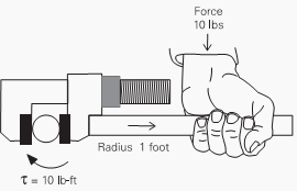
    In the English system torque is measured in pound-feet (lb-ft) or pound-inches (lb-in). If 10 lbs of force were applied to a lever 1 foot long, for example, there would be 10 lb-ft of torque.

    10 lb-ft of torque

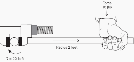
    An increase in force or radius would result in a corresponding increase in torque. Increasing the radius to 2 feet, for example, results in 20 lb-ft of torque.

    20 lb-ft of torque

    Go to back to Index ↑


    Speed

    An object in motion travels a given distance in a given time. Speed is the ratio of the distance traveled to the time it takes to travel the distance.

    Speed = Distance / Time


    Linear Speed

    The linear speed of an object is a measure of how long it takes the object to get from point A to point B. Linear speed is usually given in a form such as feet per second (f/s).

    For example, if the distance between point A and point B were 10 feet, and it took 2 seconds to travel the distance, the speed would be 5 f/s.

    Linear speed

    Go to back to Index ↑


    Angular (Rotational) Speed

    The angular speed of a rotating object is a measurement of how long it takes a given point on the object to make one complete revolution from its starting point. Angular speed is generally given in revolutions per minute (RPM).

    An object that makes ten complete revolutions in one minute, for example, has a speed of 10 RPM.

    Angular (Rotational) Speed

    Go to back to Index ↑


    Acceleration

    An object can change speed. An increase in speed is called acceleration. Acceleration occurs when there is a change in the force acting upon the object. An object can also change from a higher to a lower speed.

    This is known as deceleration (negative acceleration).

    A rotating object, for example, can accelerate from 10 RPM to 20 RPM, or decelerate from 20 RPM to 10 RPM.

    Acceleration

    Go to back to Index ↑


    Law of Inertia

    Mechanical systems are subject to the law of inertia. The law of inertia states that an object will tend to remain in its current state of rest or motion unless acted upon by an external force. This property of resistance to acceleration /deceleration is referred to as the moment of inertia.

    The English system of measurement is pound-feet squared (Ib-ft2).

    If we look at a continuous roll of paper, as it unwinds, we know that when the roll is stopped, it would take a certain amount of force to overcome the inertia of the roll to get it rolling. The force required to overcome this inertia can come from a source of energy such as a motor.

    Once rolling, the paper will continue unwinding until another force acts on it to bring it to a stop.

    Law of Inertia

    Go to back to Index ↑


    Friction

    A large amount of force is applied to overcome the inertia of the system at rest to start it moving. Because friction removes energy from a mechanical system, a continual force must be applied to keep an object in motion. The law of inertia is still valid, however, since the force applied is needed only to compensate for the energy lost.

    Once the system is in motion, only the energy required to compensate for various losses need be applied to keep it in motion.

    In the previous illustration, for example: these losses include:

    • Friction within motor and driven equipment bearings
    • Windage losses in the motor and driven equipment
    • Friction between material on winder and rollers

    Go to back to Index ↑


    Work

    Whenever a force of any kind causes motion, work is accomplished. For example, work is accomplished when an object on a conveyor is moved from one point to another.

    Work force


    Work is defined by the product of the net force (F) applied and the distance (d) moved. If twice the force is applied, twice the work is done. If an object moves twice the distance, twice the work is done.

    W = F x d

    Go to back to Index ↑


    Power

    Power is the rate of doing work, or work divided by time.

    Power = (Force x Distance) / Time

    Power = Work / Time

    In other words, power is the amount of work it takes to move the package from one point to another point, divided by the time.

    Power - rate of doing work

    Go to back to Index ↑


    Horsepower

    Power can be expressed in foot-pounds per second, but is often expressed in horsepower (HP). This unit was defined in the 18th century by James Watt. Watt sold steam engines and was asked how many horses one steam engine would replace.

    He had horses walk around a wheel that would lift a weight. He found that each horse would average about 550 foot-pounds of work per second.

    One horsepower is equivalent to 500 foot-pounds per second or 33,000 foot-pounds per minute.

    Horse power

    The following formula can be used to calculate horsepower when torque (lb-ft) and speed (RPM) are known.

    It can be seen from the formula that an increase of torque, speed, or both will cause a corresponding increase in horsepower.

    HP = (Torque x RPM) / 5250

    Power in an electrical circuit is measured in watts (W) or kilowatts (kW).

    Variable speed drives and motors manufactured in the United States are generally rated in horsepower (HP); however, it is becoming common practice to rate equipment using the International System of Units (SI units) of watts and kilowatts.

    Go to back to Index ↑

    Resource: Basics of DC Drives – SIEMENS

    Lighting Circuits Connections for Interior Electrical Installations

    $
    0
    0
    Lighting Circuits Connections for Interior Electrical Installations

    Lighting Circuits Connections for Interior Electrical Installations

    Introduction

    Electrical lines which include lighting circuits begin from the main distribution panel of the installation and each line contains three conductors: phase, neutral and ground. All three conductors reach to the terminal point of each luminaire and if it has a metal chassis the ground should be connected in the appropriate position.

    From each main distribution panel at least two lighting supply lines are leaving, so a failure on one line does not sink the entire installation in the dark. Insulation on the conductors must show the colors required by the regulations.

    The phase conductor must be brown or black, neutral conductor must be light blue and ground conductor must be yellow/green.

    To understand the circuit connections we can use various designs, including the following:

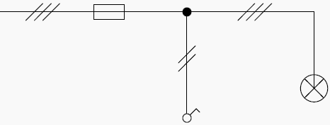
    Single line diagram

    Circuits shown are in the simplified form. These drawings show only the important elements of the lighting circuit and contain information on how to layout, number of the conductors and their cross – section.


    Analytical diagram

    Which show all the lines that connect the different parts of a circuit. These plans in large scale circuits can lose their figuration.


    Operating diagram

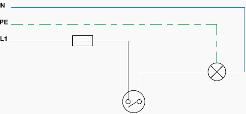
    Which show in detail the paths of electrical current. This method of design is descriptive and easy to read.

    1. Simply light circuit

    Description:

    Connection of one or more luminaire points (Lights) controlled by a simple switch. This kind of connection is used in almost all interior electrical installations.


    General diagrams

    Single line diagram

    Simple light circuit - Single line diagram

    Simple light circuit - Single line diagram


    Analytical diagram

    Simply light circuit - Analytical diagram

    Simply light circuit - Analytical diagram

    Operating diagram

    Simply light circuit - Operating diagram

    Simply light circuit - Operating diagram


    Important Note:

    In all lighting circuits a ground cable must be installed. Usually the luminaires for residential use belong in the next two categories:

    • Protection Class I: The device is grounded. The ground wire (yellow / green) must be connected to the clip marked with ground symbol.
    • Protection class II: The device is double insulated and cannot be connected to the ground.

    Go to back to Content ↑

    2. Selector switch lighting circuit (Comitater)

    Description:

    A connection of two groups of lamps controlled by a single point. The connection is usually used in chandeliers.


    General diagrams

    Single line diagram

    Selector switch lighting circuit - Single line diagram

    Selector switch lighting circuit - Single line diagram


    Analytical diagram

    Selector switch lighting circuit - Analytical diagram

    Selector switch lighting circuit - Analytical diagram


    Important Note:

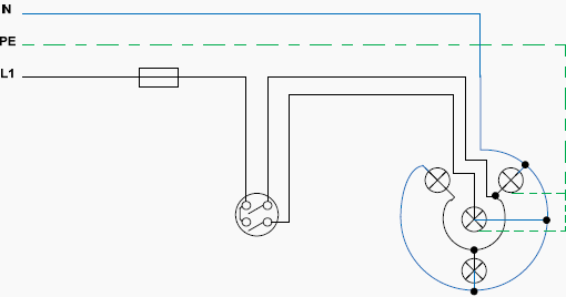
    During the design of various electrical circuits we pay attention to draw them in break mode (OFF), unless there are compelling reasons to the contrary. Above the circuit is ‘closed’, feeding all the lights.


    Operating diagram

    Selector switch lighting circuit - Operating diagram

    Selector switch lighting circuit - Operating diagram


    Go to back to Content ↑

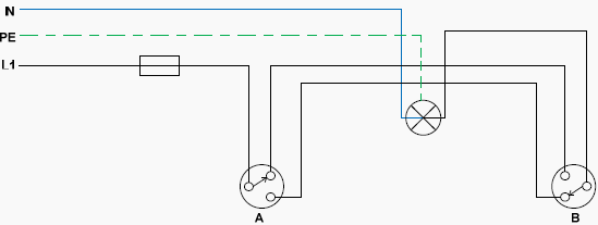
    3. Two-way switching lighting circuit (Two extreme switches Aller–Retour)

    Description:

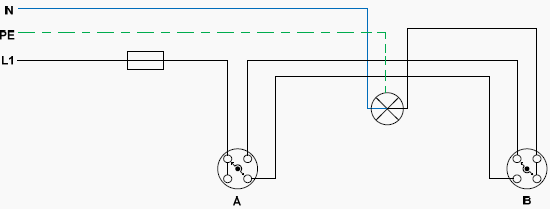
    Control of a lighting circuit from two points (A and B). This type of circuit is used in hallwaysrooms with two entrances, stairs, bedrooms, e.t.c.


    General diagrams

    Single line diagram

    Two-way switching lighting circuit - Single line diagram

    Two-way switching lighting circuit - Single line diagram

    Analytical diagram

    With rotary switches

    Two-way switching lighting circuit - Analytical diagram with rotary switches

    Two-way switching lighting circuit - Analytical diagram with rotary switches


    With pushbutton switches

    Two-way switching ighting circuit - Analytical diagram with pushbutton switches

    Two-way switching ighting circuit - Analytical diagram with pushbutton switches

    Operating diagram

    With rotary switches

    Two-way switching lighting circuit - Operating diagram with rotary switches

    Two-way switching lighting circuit - Operating diagram with rotary switches


    With pushbutton switches

    Two-way switching lighting circuit - Operating diagram pushbutton switches

    Two-way switching lighting circuit - Operating diagram pushbutton switches


    Go to back to Content ↑

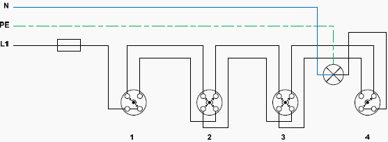
    4. Switching lighting circuit (Aller–Retour) with two extreme switches and one or more intermediate switches

    Description:

    Control of a lighting circuit from three or more points. This type of circuit is used in large roomslong corridors, staircases and generally in large rooms.


    General diagrams

    Single line diagram

    Switching lighting circuit - Single line diagram

    Switching lighting circuit - Single line diagram


    Analytical diagram

    Switching lighting circuit - Analytical diagram

    Switching lighting circuit - Analytical diagram

    Operating diagram

    Switching lighting circuit - Operating diagram

    Switching lighting circuit - Operating diagram


    Go to back to Content ↑

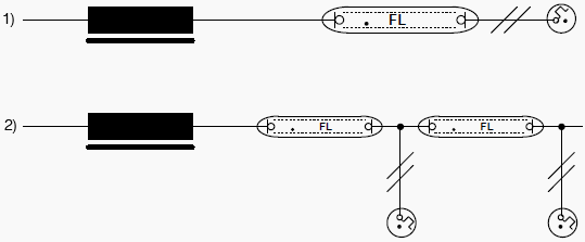
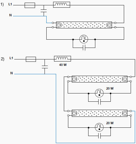
    5. Lighting circuits with fluorescent tubes

    Description:

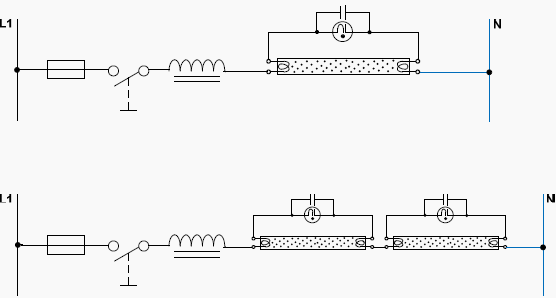
    1. Circuit of a 40W fluorescent tube, with 40W Ballast and starter.
    2. Circuit with two fluorescent tubes (20W each), with 40W Ballast and two starters (20W each)

    The fluorescent tubes are used particularly in factories, offices, for decoration and advertising or promotion of goods. In recent years fluorescent tubes are used in residential installations.


    General diagrams

    Single line diagram

    Fluorescent tubes - Single line diagram

    Fluorescent tubes - Single line diagram


    Important Note:

    In figure b) we can add more fluorescent tubes if we want in series but we should also add more starters and a more powerful ballast.


    Analitycal diagrams

    Fluorescent tubes - Analytical diagram

    Fluorescent tubes - Analytical diagram

    Operating diagrams

    Fluorescent tubes - Operating diagram

    Fluorescent tubes - Operating diagram


    Important Notes:

    In figure 2) If one of the two starters or one of the two lamps stop working, then none of the lamps will eventually function.

    The metal chassis of the lamp or the ballast’s choke should be grounded. The fluorescent tubes import reactive power to the grid. With new European Union directives, mechanical ballasts are repealed and only electronic ballasts (triac) should be used, which limit the reactive power.

    The starter and the capacitor are abolished and we have direct ignition of the lamp.

    Go to back to Content ↑

    Methods of Controlling Lightning Overvoltages in HV

    $
    0
    0
    Methods of Controlling Lightning Overvoltages in HV

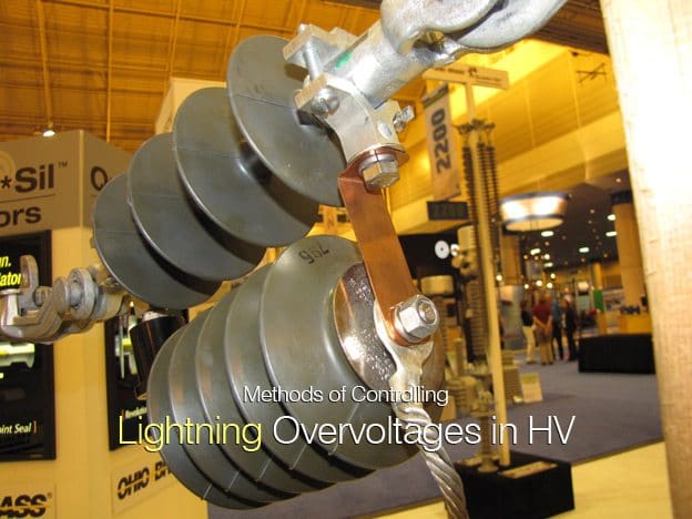
    Hubbell's improved protecta-lite transmission line arrester line has been simplified with fewer parts and less risk of parts wearing out. Several steel plated components were replaced with one copper strap. The strap makes installation easier and reduces the wear points. Vibration and wear are more important on transmission line arresters due to the fact that they are more exposed to wind and vibration.

    Introduction

    For well shielded transmission lines, the backflashover condition, close to the substation, is of prime concern for determining the location and number of surge arresters required to achieve insulation coordination of the substation for lightning surges.

    The risk of a backflashover can be reduced by keeping the tower foot impedances to a minimum, particularly close to the substation (first five to seven towers).

    The terminal tower is usually bonded to the substation earth mat and will have a very low grounding impedance (1 ohm).

    However, the procedure for ‘gapping’ down on the first three or four towers where line co-ordinating gaps are reduced in an attempt to reduce incoming voltage surges will increase the risk of a ‘close-in’ backflashover.


    Location of Surge Arresters

    Considering the system shown in Figure 1, where the transmission line is directly connected to a 420 kV GIS (Gas Insulated Switchgear), a computer model can be created to take into account the parameters previously discussed.

    A transient study would reveal the level of lightning stroke current required to cause a backflashover.

    System schematic diagram

    Figure 1 - System schematic diagram


    Then according to the number of line flashes 100 km/yr calculated for the transmission line and by using the probability curve for lightning current amplitude, a return time for this stroke current can be assessed (Le. 1 in 400 yrs, 1 in 10 yrs, etc.) in, say, the first kilometre of the line.

    The voltage then arriving at the substation can be evaluated and compared with the LIWL (Lightning impulse withstand level) for the substation equipment.

    The open-circuit-breaker condition must be studied here, since if the line circuit-breaker is open the surge voltage will ‘double-up’ at the open terminal. Various levels of stroke current can be simulated at different tower locations and the resultant substation overvoltages can be assessed.

    If it is considered that the LIWL of the substation will be exceeded or that there is insufficient margin between the calculated surge levels and the LIWL to produce an acceptable risk, then surge arrester protection must be applied.

    The rating of the MOA (metal oxide surgearresters) will have been assessed from TOV (Temporary overvoltage) requirements, and from the manufacturer’s data a surge arrester model can be included in the system model. Repeating the various studies will reveal the protective level of the arrester and from this the safety factor for this system configuration can be assessed.

    IEC 60071 recommends a safety factor of 1.25 for 420 kV equipment (safety factor = LIWL / protective level).

    The surge arrester current calculated for this condition should be the ‘worst’ case and can therefore be used to assess the nominal discharge current requirement of the surge arrester (5 kA, 10 kA or 20 kA).

    (IEC 60091-1 is the international standard for surge arresters [16], and an accompanying guide isavailable which contains detailed information on the application of surge arresters).

    To make full use of the MOA protective level the arrester should be placed as close as possible to the equipment being protected.

    In the case of the open line circuit-breaker this may well be 10-20 m distance.

    Dependent on the rate of rise of the surge voltage, a voltage greater than the residual voltage at the surge arrester location will be experienced at the terminals of the open-circuit-breaker. This must be taken into account when assessing the substation overvoltage.

    Figure 2 illustrates the surge voltage profile of the GIS (Gas Insulated Switchgear) with the line circuit-breaker closed. It shows that additional surge arresters may be required because of the distances involved in the layout of the substation.

    Analysis of lightning surge for gas insulated substation

    Figure 2 - Analysis of lightning surge for gas insulated substation


    It then follows that surge arresters have a ‘protective length’  which is sensitive to the rate of rise of the incoming surge voltage, and this must be taken into consideration when assessing the lighting overvoltage on equipment remote from the surge arrester.

    Resource: High voltage engineering and testing - Hugh M. Ryan

    How Distribution Systems Control Customer Loads?

    $
    0
    0
    How Distribution Systems Control Customer Loads?

    How Distribution Systems Control Customer Loads? (on photo: Control Room of Power Distribution Utility)

    Distribution Systems

    Distribution systems obviously exist to supply electricity to end users, so loads and their characteristics are important. Utilities supply a broad range of loads, from rural areas with load densities of 10 kVA/mi2 to urban areas with 300 MVA/mi2. A utility may feed houses with a 10- to 20-kVA peak load on the same circuit as an industrial customer peaking at 5 MW.

    The electrical load on a feeder is the sum of all individual customer loads. And the electrical load of a customer is the sum of the load drawn by the customer’s individual appliances.

    Customer loads have many common characteristics. Load levels vary through the day, peaking in the afternoon or early evening.


    Load characteristics

    Several definitions are used to quantify load characteristics at a given location on a circuit:

    1. Demand
    2. Load factor
    3. Coincident factor
    4. Diversity factor
    5. Responsibility factor

    Demand

    The load average over a specified time period, often 1520, or 30 minutes.

    Demand can be used to characterize real powerreactive power, total power, or current.

    Peak demand over some period of time is the most common way utilities quantify a circuit’s load. In substations, it is common to track the current demand.

    Go to Index ↑


    Load factor

    The ratio of the average load over the peak load. Peak load is normally the maximum demand but may be the instantaneous peak. The load factor is between zero and one.

    A load factor close to 1.0 indicates that the load runs almost constantly. A low load factor indicates a more widely varying load. From the utility point of view, it is better to have high load-factor loads.

    Load factor is normally found from the total energy used (kilowatt-hours) as:

    Load factor formula

    where:

    LF = load factor
    kWh = energy use in kilowatt-hours
    dkW = peak demand in kilowatts
    h = number of hours during the time period

    Go to Index ↑


    Coincident factor

    The ratio of the peak demand of a whole system to the sum of the individual peak demands within that system. The peak demand of the whole system is referred to as the peak diversified demand or as the peak coincident demand.

    The individual peak demands are the noncoincident demands.

    The coincident factor is less than or equal to one. Normally, the coincident factor is much less than one because each of the individual loads do not hit their peak at the same time (they are not coincident).

    Go to Index ↑


    Diversity factor

    The ratio of the sum of the individual peak demands in a system to the peak demand of the whole system. The diversity factor is greater than or equal to one and is the reciprocal of the coincident factor.

    Go to Index ↑


    Responsibility factor

    The ratio of a load’s demand at the time of the system peak to its peak demand. A load with a responsibility factor of one peaks at the same time as the overall system.

    The responsibility factor can be applied to individual customers, customer classes, or circuit sections.

    Go to Index ↑

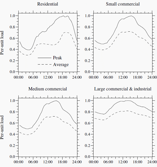
    The loads of certain customer classes tend to vary in similar patterns.

    Commercial loads are highest from 8 a.m. to 6 p.m. Residential loads peak in the evening. Weather significantly changes loading levels. On hot summer days, air conditioning increases the demand and reduces the diversity among loads. At the transformer level, load factors of 0.4 to 0.6 are typical (Gangel and Propst, 1965).

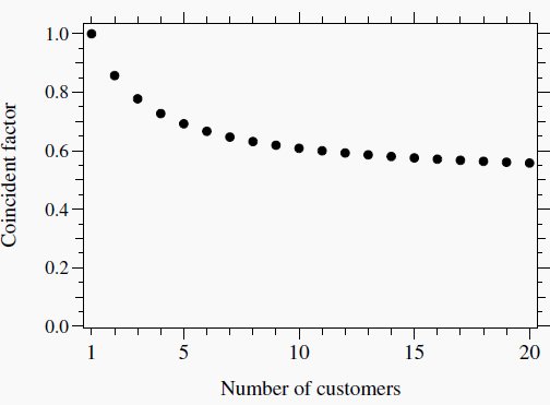
    Several groups have evaluated coincidence factors as a function of the number of customers. Nickel and Braunstein (1981) determined that one curve fell roughly in the middle of several curves evaluated.

    Used by Arkansas Power and Light, this curve fits the following:

    Responsibility factor formula

    where n is the number of customers (see Figure 1).

    Coincident factor average curve for utilities

    Figure 1 - Coincident factor average curve for utilities


    At the substation level, coincidence is also apparent. A transformer with four feeders, each peaking at 100 A, will peak at less than 400 A because of diversity between feeders.

    The coincident factor between four feeders is normally higher than coincident factors at the individual customer level.

    Expect coincident factors to be above 0.9.

    Each feeder is already highly diversified, so not much more is gained by grouping more customers together if the sets of customers are similar. If the customer mix on each feeder is different, then multiple feeders can have significant differences.

    If some feeders are mainly residential and others are commercial, the peak load of the feeders together can be significantly lower than the sum of the peaks.

    Daily load profiles for Pacific Gas and Electric

    Figure 2 - Daily load profiles for Pacific Gas and Electric (2002 data)


    For distribution transformers, the peak responsibility factor ranges from 0.5 to 0.9 with 0.75 being typical (Nickel and Braunstein, 1981). Different customer classes have different characteristics (see Figure 2 for an example).

    Residential loads peak more in the evening and have a relatively low load factor. Commercial loads tend to be more 8 a.m. to 6 p.m., and the industrial loads tend to run continuously and, as a class, they have a higher load factor.

    Resource: Electric Power Distribution Equipment and Systems - Thomas A Short
    (Get this book from Amazon)

    The Role of Fuse in Low Voltage Systems

    $
    0
    0
    The Role of Fuses in Low Voltage Systems

    The Role of Fuses in Low Voltage Systems (on photo: ETI low voltage fuse-links)

    Introduction to Fuses

    A fuse is the very important protective device used to automatically disconnect a live circuit when a predetermined value of current & or time of predetermined current is exceeded.  To simplify, fuse is actually the wire designed to melt, and thereby open the circuit, if the current exceeds a predetermined value.

    The disconnection mean by fuse is based on the applicable protection philosophies.

    Fuses are available in AC and DC circuits from extra low voltages to high voltages. A circuit breaker also does similar type of function as a fuse.

    Unlike a circuit breaker, fuse is self-destructive which requires replacement after it disconnects a circuit.

    Some CBs also perform switching function with or without current flowing in the circuit. A hybrid device is a fused-disconnect switch which has a fuse associated with a load/no-load disconnecting switch (may be group operated or single pole type).

    Some fuses provide additional function such as operation indication (dropout, burnt mark, a plunger etc.), driving an aux contact to close, limiting the peak current etc.


    General Protection Philosophies in LV System

    Based on the application and philosophies, various protection means are applied. The following are general groups on which the protection systems are designed:

    1. Prevention of Electric Shocks

    1. Direct contact
    2. Indirect contact

    Dealing with Electric shocks due to Direct Contact:

    1. Preventing a current from passing through the human body or any livestock
    2. Limiting the current which can pass through the human body or any livestock to lower than the shock current

    Dealing with Electric shocks due to Indirect Contact:
    In dealing with protection against indirect contact under single fault conditions, regulations permits the two methods given above for direct contact and additionally automatic disconnection of supply in a determined time on occurrence of a fault which is likely to cause a current to flow through the body in contact with exposed conductive


    2. Prevention against Thermal effects

    1. Preventing ignition of flammable material due to heat or arc
    2. Preventing burns to human or livestock
    3. Preventing degradation or impairment of the Equipment

    3. Prevention against Over Current

    Preventing injury to human or livestock or equipment due to thermal as  well as electromechanical stresses due to the overcurrent.


    4. Prevention against Fault Current

    Preventing the conductors or any other part carrying Short-circuit from attaining temperature greater than its design value and electrodynamic-withstand levels (peak current).


    Prevention against Over Voltages

    Preventing the damage to property, equipment, human or livestock due to:

    1. Over voltages which cause faults between circuits supplied at different  voltages
    2. Over voltages which arise due to switching and atmospheric actions.

    Fuse Types

    Various fuses exist in electric circuits. Our first task is to identify the fuse application and type. There are general three types of fuses found in an electric circuits categorized as follows:

    Miniature Fuses

    Miniature Fuses

    Miniature Fuses


    These Fuses are identified as type:

    • FF (Ultra Rapid)
    • F or QA or QB (Fast Blow)
    • M or MD (Medium Blow)
    • T or SB (Slow Blow)
    • TT (Ultra Slow)

    Bottle Fuses

    Bottle fuses (DIAZED, NEOZED)

    Bottle fuses (left: DIAZED, right: NEOZED)


    These Fuses are identified as type:

    • Diazed 500V Fuses, D1 (E16), D11 (E27), D111 (E33)
    • Neozed 380V Fuses, D01 (E14), D02 (E18)
    • Silazed Ultra Rapid Fuses, D11 (E27), D111 (E33)

    Industrial Fuses

    NH type with blades

    NH type with blades


    These Fuses are identified as type:

    • aR, gR or uR (Ultra Rapid)
    • gL or gG (General Line)
    • gM (Motor rated general Line)
    • aM (Motor rated)
    • gF or gTF (Transformer, Cable Protection)
    • gB (Mining Fuses)

    NH fuses are typically used for distribution applications to large electrical devices such as motors, drives and similar. They are available in seven sizes from 3A to 1600A, but it depends on manufacturer.

    NH fuses have knife blades at both ends which mount into one or three pole fuse basis/holder. Fuse holder can be installed on panel or DIN rail.

    Operating classes:

    gL/gG

    Offers protection at every level. Typically used for distribution circuit or resistive loads.

    aM

    Offers protection for all low voltage motors. Fast acting short circuit protection, but slow acting overload protection.

    aR

    Semiconductor protection partial range, overload and short circuit protection for devices such as diodes, SCRs etc.

    gR

    Semiconductor protection, full range overload and short circuit protection for devices such as diodes, SCRs etc.


    Fuse Current Ampere Rating

    Generally, a fuse current rating shall not be less than the full load rating of the  circuit it is protecting.

    Overloads or overcurrents if occur frequently will degrade the fuse performance  and hence there shall be clear idea of overloads which occur frequently or infrequently.

    Overcurrents typically occur in motor circuits, charging (energizing) a reactive equipment like:

    • Capacitor,
    • Shunt Reactor,
    • Transformer etc.

    Overloads occur due to diversity in loads (based on max load, connected load or contingency loads, increased loads, process jams, mechanical failures etc.). some overcurrents or overloads are requires the circuits to be disconnected, while others may be transient requiring fuses to ride through them (in coordination with some other protective device upstream or downstream).

    Obviously, upstream device operation before the fuse is designed to enhance interruption capability.


    How It’s Made Fuses? (VIDEO)

    Cant see this video? Click here to watch it on Youtube.

    Resource: Low Voltage Systems and Protective Fuses in Commercial and Industrial Systems – S.R. Javed Ahmed

    21 Safety Rules for Working with Electrical Equipment

    $
    0
    0
    21 Safety Rules for Working with Electrical Equipment

    21 Safety Rules for Working with Electrical Equipment


    A safe work environment is not always enough to control all potential electrical hazards. You must be very cautious and work safely. Safety rules help you control your and others risk of injury or death from workplace hazards.

    If you are working on electrical circuits or with electrical tools and equipment, you need to use following golden safety rules:


    21 Golden Safety Rules

    Rule no. 1

    Avoid contact with energized electrical circuits. Please don’t make fun of this rule if you already know this (and you probably already know if you are reading these lines) and remember that if something bad occurs – you probably won’t have second chance. That’s not funny.


    Rule no. 2

    Treat all electrical devices as if they are live or energized. You never know.


    Rule no. 3

    Disconnect the power source before servicing or repairing electrical equipment.

    The only way to be sure.


    Rule no. 4

    Use only tools and equipment with non-conducting handles when working on electrical devices.

    Easy to check.


    Rule no. 5

    Never use metallic pencils or rulers, or wear rings or metal watchbands when working with electrical equipment. This rule is very easy to forget, especially when you are showing some electrical part pointing with metallic pencil.

    Always be aware.


    Rule no. 6

    When it is necessary to handle equipment that is plugged in, be sure hands are dry and, when possible, wear nonconductive gloves, protective clothes and shoes with insulated soles.

    Remeber: gloves, clothes and shoes.

    Safety clothes, gloves and shoes

    Safety clothes, gloves and shoes


    Rule no. 7

    If it is safe to do so, work with only one hand, keeping the other hand at your side or in your pocket, away from all conductive material. This precaution reduces the likelihood of accidents that result in current passing through the chest cavity.

    If you ever read about current passing through human body you will know, so remember – work with one hand only.

    If you don’t clue about electric current path through human body, read more in following technical articles:


    Rule no. 8

    Minimize the use of electrical equipment in cold rooms or other areas where condensation is likely. If equipment must be used in such areas, mount the equipment on a wall or vertical panel.


    Rule no. 9

    If water or a chemical is spilled onto equipment, shut off power at the main switch or circuit breaker and unplug the equipment.

    Very logical. NEVER try to remove water or similar from equipment while energized. Afterall, it’s stupid to do so.


    Rule no. 10

    If an individual comes in contact with a live electrical conductor, do not touch the equipment, cord or person. Disconnect the power source from the circuit breaker or pull out the plug using a leather belt.

    Tricky situation, and you must be very calm in order not to make the situation even worse.

    Like in previous rules – Always disconnect the power FIRST.

    Always disconnect the power FIRST

    Always disconnect the power FIRST


    Rule no. 11

    Equipment producing a “tingle” should be disconnected and reported promptly for repair.


    Rule no. 12

    Do not rely on grounding to mask a defective circuit nor attempt to correct a fault by insertion of another fuse or breaker, particularly one of larger capacity.


    Rule no. 13

    Drain capacitors before working near them and keep the short circuit on the terminals during the work to prevent electrical shock.


    Rule no. 14

    Never touch another person’s equipment or electrical control devices unless instructed to do so.

    Don’t be too smart. Don’t try your luck.


    Rule no. 15

    Enclose all electric contacts and conductors so that no one can accidentally come into contact with them.

    If applicable do it always, if not be very carefull.


    Rule no. 16

    Never handle electrical equipment when hands, feet, or body are wet or perspiring, or when standing on a wet floor.

    Remeber: Gloves and shoes


    Rule no. 17

    When it is necessary to touch electrical equipment (for example, when checking for overheated motors), use the back of the hand. Thus, if accidental shock were to cause muscular contraction, you would not “freeze” to the conductor.


    Rule no. 18

    Do not store highly flammable liquids near electrical equipment.


    Rule no. 19

    Be aware that interlocks on equipment disconnect the high voltage source when a cabinet door is open but power for control circuits may remain on.

    Read the single line diagram and wiring schemes – know your switchboard. 


    Rule no. 20

    De-energize open experimental circuits and equipment to be left unattended.


    Rule no. 21

    Do not wear loose clothing or ties near electrical equipment. Act like an electrical engineer, you are not on the beach.


    Example of human stupidity and ignorance of basic safety

    Electrical safety, come on… I guess we’ll never know did the cord extension drop into water… Hope not.

    Example of stupidity

    Example of stupidity


    Rogowski Coil Construction

    $
    0
    0
    Rogowski Coil Construction

    Rogowski Coils For Precision Measurements and Protection


    Figure 1 shows the construction of a Rogowski coil, an air-core current transformer that is especially well suited to measuring ripple currents in the presence of a DC component or measuring pulsed currents.

    The raw output is proportional to the derivative of the current, and the current can be recovered by an integrator or a low-pass filter.

    The output voltage is given by:

    Output voltage formula

    Rogowski coil construction

    Figure 1 - Rogowski coil construction


    Where: 

    n is the number of turns
    A is the cross sectional area of the toroid
    s is the centerline circumference

    The coil is wound on an air-core form of suitable size for the current conductor. The winding should be applied in evenly spaced turns in one direction only-not back and forth-so that capacitive effects are minimized.

    The far end of the winding should be brought back around the circumference of the coil to eliminate the turn formed by the winding itself. The winding must generally be shielded, since the output voltage is relatively low. The shield should be applied so that it does not form a shorted turn through the opening, and the coil should be equipped with an integral shielded output lead with the ground side connected to the coil shield.

    Output from the Rogowski coil can either be integrated with a passive network as an R/C low-pass filter or with an operational amplifier.

    The advantage of the R/C network is that no power is required for operation. The disadvantages are that it cannot be gated and that the output voltage becomes very low if low-frequency response is required.

    Although a toroidal form is shown in the sketch, Rogowski coils are commercially available that are wound in the form of a very long, flexible solenoid that can be wrapped around a conductor and then secured mechanically.

    Rogowski coils are largely unaffected by stray fields that have a constant amplitude across the coil. A field gradient across the coil, however, will introduce a spurious output if the field is time varying.

    It is good practice to make the coil as small as possible within the electrical and physical constraints of the equipment.

    The Rogowski coil can be calibrated from a 50/60-Hz current assuming, of course, that the bandpass of the filter or integrator extends down to those frequencies.

    Resource: Electronics Design : A Practitioner’s Guide - eith H. Sueker


    Power Line Carrier Communication (PLCC)

    $
    0
    0
    Power Line Carrier Communication (PLCC)

    Power Line Carrier Communication - PLCC (photo: Zanith Transformers & Swithgears Pvt. Ltd)

    Content

    1. Coupling Capacitor
    2. Line trap Unit
    3. Transmitters and Receivers
    4. Hybrids and Filters
    5. Line Tuners
    6. Master Oscillator and Amplifiers
    7. Protection and earthing of coupling equipment
  8. Advantages of Digital PLCC over Analog ones
  9. Typical signal to noise ratio calculation by considering a line of 295 kilometers
  10. SNR (Signal-to-Noise Ratio) Calculation
  11. Introduction

    Use of PLCC in modern electrical power system is mainly for telemetry and telecontrol. Tele means remote. Telemetry refers to science of measurement from remote location.

    Different types of data transmission system can be used depending upon the network requirement and conditions.

    Main data transmission system for telemetry and telecontrol are:

    1. Use of telephone lines
    2. Use of separate cables
    3. Power Line carrier communication
    4. Radio wave micro wave channel
    PLCC Panel Block Diagram

    PLCC Panel Block Diagram


    For large power system power line carrier communication is used for data transmission as well as protection of transmission lines. Carrier current has a frequency range of 30 to 200 kHz in USA and 80 to 500 kHz in UK.

    Each end of transmission line is provided with identical PLCC equipment consisting of equipment:

    1. Transmitters and Receivers
    2. Hybrids and Filters
    3. Line Tuners
    4. Line Traps
    5. Power amplifier
    6. Coupling capacitors

    Distance protection relay in relay panel at one end of the transmission line gets the input from CT and CVT in line. The output of relay goes to modem of PLCC.

    PLCC scheme

    PLCC scheme


    The output of PLCC goes to coupling capacitor and then to transmission line and travels to another end where it is received through coupling capacitor and inputted to relay and control panel at that end.

    Go to Content ↑


    Major goal/Application of PLCC

    PLCC in modern electrical power system substation is mainly used for following purpose:

    1. Carrier protection relaying of transmission line so that:
    • Inter trip command can be issued by relay due to tripping of circuit breaker at any one end.
    • To trip the line circuit breaker nearest to the fault, this is done by:
      a) Distance protection relay (V/I characteristics)
      b) Differential comparison method
      c) Phase comparison method
  12. Station to station communication between operating personnel
  13. Carrier telemetring, electrical quantities that are telemetered are kW, kVA, kVAR, Voltage and Power factor etc.
    Following methods are used for telemetring as well as telecontrol:
    • Simplex
    • Duplex
    • Multiplex
    • Time division Multiplex

    Many factors will affect the reliability of a power line carrier (PLC) channel.

    The goal is to get a signal level to the remote terminal that is above the sensitivity of the receiver, and with a signal-to-noise ratio (SNR) well above the minimum, so that the receiver can make a correct decision based on the information transmitted.

    If both of these requirements are met then the PLC channel will be reliable.

    The factors affecting reliability are:

    1. The amount of power out of the transmitter.
    2. The type and number of hybrids required to parallel transmitters and receivers.
    3. The type of line tuner applied.
    4. The size of the coupling capacitor in terms of capacitance.
    5. The type and size, in terms of inductance, of the line trap used.
    6. The power line voltage and the physical configuration of the power line.
    7. The phase(s) to which the PLC signal is coupled.
    8. The length of the circuit and transpositions in the circuit.
    9. The decoupling equipment at the receiving terminal (usually the same as the transmitting end).
    10. The type of modulation used to transmit the information, and the type of demodulation circuits in the receiver.
    11. The received signal-to-noise ratio (SNR).

    The above list may not be all inclusive, but these are the major factors involved in the success or failure of a PLC channel.

    Go to Content ↑


    Main Components of PLCC

    1. Coupling Capacitor

    PLCC component - Coupling Capacitor

    PLCC component - Coupling Capacitor


    Coupling capacitor connects the carrier equipment to the transmission line. The coupling capacitor’s capacitance is of such a value that it offers low impedance to carrier frequency (1/ωC) but high impedance to power frequency (50 Hz).

    For example 2000pF capacitor offers 1.5MΩ to 50Hz but 150Ω to 500kHz.

    Thus coupling capacitor allows carrier frequency signal to enter the carrier equipment.

    To decrease the impedance further and make the circuit purely resistive so that there is no reactive power in the circuit, low impedance is connected in series with coupling capacitor to form resonance at carrier frequency.

    Go to Content ↑


    2. Line trap Unit

    The carrier energy on the transmission line must be directed toward the remote line terminal and not toward the station bus and it must be isolated from bus impedance variations. This task is performed by the line trap.

    The line trap is usually a form of a parallel resonant circuit which is tuned to the carrier energy frequency.

    A parallel resonant circuit has high impedance at its tuned frequency, and it then causes most of the carrier energy to flow toward the remote line terminal. The coil of the line trap provides a low impedance path for the flow of the power frequency energy.

    Since the power flow is rather large at times, the coil used in a line trap must be large in terms of physical size.

    Hence a line trap unit/Wave trap is inserted between busbar and connection of coupling capacitor to the line. It is a parallel tuned circuit comprising of inductance (L) and capacitance (C). It has low impedance (less than 0.1?) for power frequency (50 Hz) and high impedance to carrier frequency.

    This unit prevents the high frequency carrier signal from entering the neighboring line.

    Go to Content ↑


    3. Transmitters and Receivers

    The carrier transmitters and receivers are usually mounted in a rack or cabinet in the control house, and the line tuner is out in the switchyard.

    This then means there is a large distance between the equipment and the tuner, and the connection between the two is made using a coaxial cable.

    PLCC component - Transmitters and receivers

    PLCC component - Transmitters and receivers


    The coaxial cable provides shielding so that noise cannot get into the cable and cause interference. The coaxial cable is connected to the line tuner which must be mounted at the base of the coupling capacitor.

    If there is more than one transmitter involved per terminal the signal must go through isolation circuits, typically hybrids, before connection to the line tuner.

    Go to Content ↑


    4. Hybrids and Filters

    The purpose of the hybrid circuits is to enable the connection of two or more transmitters together on one coaxial cable without causing intermodulation distortion due to the signal from one transmitter affecting the output stages of the other transmitter. Hybrids may also be required between transmitters and receivers, depending on the application.

    The hybrid circuits can, of course, cause large losses in the carrier path and must be used appropriately. High/low-pass and band-pass networks may also be used, in some applications, to isolate carrier equipment from each other.


    5. Line Tuners

    The purpose of the line tuner in conjunction with the coupling capacitor is to provide low impedance path for the carrier energy to the transmission line and a high impedance path to the power frequency energy.

    The line tuner/coupling capacitor combination provides a low impedance path to the power line by forming a series resonant circuit tuned to the carrier frequency.

    On the other hand, the capacitance of the coupling capacitor is high impedance to the power frequency energy. Even though the coupling capacitor has high impedance at power frequencies, there must be a path to ground in order that the capacitor may do its job. This function is provided by the drain coil, which is in the base of the coupling capacitor. The drain coil is designed to be low impedance at the power frequency and because of its inductance it will have high impedance to the carrier frequency.

    Thus the combination of the line tuner, coupling capacitor, and the drain coil provide the necessary tools for coupling the carrier energy to the transmission line and blocking the power frequency energy. One last function of the line tuner is to provide matching of impedance between the carrier coaxial cable, usually 50 to 75 ohms, and the power line which will have an impedance of 150 to 500 ohms.

    Go to Content ↑


    6. Master Oscillator and Amplifiers

    High frequency carrier signal is generated in oscillator.

    Oscillator can be crystal oscillator with which operation for a particular bandwidth can be achieved. The output voltage of a oscillator is held constant by voltage stabilizer.

    The output of oscillator is fed to amplifier so that loses in transmission can be compensated. Losses occurring in carrier current is termed as attenuation of carrier signal.

    They are mainly: Losses in coupling equipment which are constant losses for a given carrier frequency bandwidth.

    PLCC component - Master oscillator and amplifiers

    PLCC component - Master oscillator and amplifiers


    Line losses vary with length line, size of line, weather condition etc…These losses for underground line is more than overhead line.

    Frequency spacing is a process using different carrier frequency in two adjacent transmission lines. Wave trap/Line trap help in accomplishing this.

    Go to Content ↑


    7. Protection and earthing of coupling equipment

    Over voltage can be caused due to lightning, switching and sudden loss of load etc.

    They produce stress on coupling equipment and line trap units. Non linier resistor in series with protective gap is connected across the line trap unit and inductor of coupling unit.

    The gap is adjusted to spark at a set value of over voltage.

    Protection and earthing of coupling equipment

    Protection and earthing of coupling equipment


    Coupling unit and PLCC equipment are earthed through a separate and dedicated system, so that ground potential rise of station earthing system does not affect the reference voltage level/Power supply common ground of the PLCC equipment.

    In this regard that is earthing of PLCC and other communication/Instrumentation/Electronic equipment please refer to NEC Article 645 for data centers (IT equipment.)

    Advantages of Digital PLCC over Analog ones

    1. Immune to noise in processing and storage stages, as it is completely digital.
    2. Digital: Require less no. of circuits (hardware), since Digital Processor is a single chip.
    3. Processing is accurate and reliable.
    4. Frequency conversion is done in a single step (Digital Conversion).
    5. Digital processing allows the application of a wide range of mathematics. (Analog processing is limited by the availability of devices to perform desired functions, while)
    6. Equalization is perfect: High-resolution digital filtering gives very flat filter response as desired.
    7. The performance of digital circuits, opposed to analog, is relatively independent of actual component values in the implementing circuit. Therefore, digital systems more reliably reproduce the desired responses in spite of temperature variations or component aging.
    8. In addition, in digital circuits there is little need for component matching.
    9. Simplified Production: Lower Parts count and improved testability.

    Power Line Carrier (PLC) Signal propagation along high voltage lines depends entirely on the construction of transmission lines, mainly on the configuration and characteristics of all conductors and on the ground resistance optimum coupling allows to make the best use of a given transmission line.

    Transposition may introduce additional attenuation which can generally not be predicted with simple rules. Most transposition schemes result in high attenuation poles at certain frequencies such frequencies cannot be used for PLC communications.

    Forbidden Frequency Ranges may be determined as explained in CIGRE Paper 35-02, Senn/Morf – Optimum PLC Arrangement on Transposed Single Circuit power Lines – (August, 1984)

    In critical cases, however, computer calculation may be necessary, for which the following data is required:

    1. Height of each conductor above ground (at the towers)
    2. Sag of conductors (between towers)
    3. Horizontal distance (between conductors)
    4. Number of conductors per phase (single or if bundle spacing)
    5. Outer diameter of conductors, material of conductors
    6. Number of strands at the circumference (outer strands)
    7. Diameter of strands
    8. Same information (a) to (g) for ground wires
    9. Total length of transmission line
    10. Sketch of phasing arrangement showing type and number of transpositions and distance between transpositions (if double system, each scheme required separately)
    11. Earth resistivity in Ohm meters, if not known, state whether around 300 or 1000 or 3000 communication separately.
    12. Coupling arrangement (phase to ground of phase to phase)
    13. Available carrier frequency range

    Go to Content ↑


    Typical signal to noise ratio calculation by considering a line of 295 kilometers

    Frequency line section: 140/144 KHz
    Line Voltage: 400 KV
    Line configuration: 3 transpositions at equal distance
    Line length: 295 Kms
    Conductor diameter: 31.77 mm
    No. of bundles per conductor: Two

    Overall loss = Line attenuation + Coupling loss

    Line attenuation (aL) = a1 x L + 2aC + aadd

    Where:

    a1 = attenuation constant of the lowest loss made in dB per Km
    ac = model conversion loss in dB
    aadd = additional loss caused by discontinuities e.g. coupling circuits, transposition etc. in dB
    a1 is a constant which depends upon
    f = frequency in KHz
    d = conductor diameter in mm
    n = No. of bundles

    Line configuration = No of transposition at equal intervals

    Upon substituting corresponding values with certain approximation we get a1:

    a1 = 0.029 dB/Km

    Line attenuation, aL = 0.029 x 295 + 2 x 0 + 10 = 8.55 + 10 = 18.55 dB

    Coupling Loss = Loss in Coupling equipment + tapping loss + paralleling loss + by pass losses in case of bypasses + cable loss.

    = 2 + 2.6 + 1 + 0 + 0.5
    = 6.1 dB

    Overall loss = Line attenuation + Coupling loss = 18.55 + 6.1 = 24.65 dB

    Go to Content ↑


    SNR (Signal-to-Noise Ratio) Calculation

    Signal level (speech) = +35 dB & 38 dB (Corresponding to 20 Watt (43 dBm PEP) and 40 watts respectively)

    Noise level (Corona noise) in 2.2 KHz bandwidth = -13.5 dB
    Correction considering Psophometric factor = -2.0 dB
    Noise level in speech band (300 – 2400 Hz) = -15.5 dB
    Equipment noise above external = -60 dBm is very low corresponding to noise so not considered in calculation
    Signal level (speech) at receiver side on line side = +35 – (Line attenuation + Coupling loss)

    = +35 – (18.55 + 6.1) = +35 – 24.65 = 10.35 dB

    Signal to noise ratio = (Signal level (speech) at receiver side on line side – Noise level in speech band)

    = +10.35 -(-15.5 dB) = 25.85 dB (considering PLC terminal power output as 20 watts)

    = 28.85 dB (considering PLC terminal power output as 40 watts which is recommended for better SNR).

    Go to Content ↑
    Enhance Grid Reliability With Hybrid HVDC Breaker

    $
    0
    0
    The Hybrid HVDC Breaker by ABB

    The Hybrid HVDC Breaker by ABB - The hybrid design has negligible conduction losses, while preserving ultra-fast current interruption capability.

    Content

    1. Introduction to HHVDC
    2. How does Hybrid HVDC Breaker work? (VIDEO)
    3. Hybrid HVDC Breaker Construction
    4. Proactive control
    5. Prototype Design Of The Hybrid HVDC Breaker
    6. Comparison/Summary

    Introduction

    The advance of voltage source converter-based (VSC) high-voltage direct current (HVDC) transmission systems makes it possible to build an HVDC grid with many terminals.

    Compared with high-voltage alternating current (AC) grids, active power conduction losses are relatively low and reactive power conduction losses are zero in an HVDC grid.

    This advantage makes an HVDC grid more attractive.

    However, the relatively low impedance in HVDC grids is a challenge when a short circuit fault occurs, because the fault penetration is much faster and deeper.

    Consequently, fast and reliable HVDC breakers are needed to isolate faults and avoid a collapse of the common HVDC grid voltage.

    Furthermore, maintaining a reasonable level of HVDC voltage is a precondition for the converter station to operate normally. In order to minimize disturbances in converter operation, particularly the operation of stations not connected to the faulty line or cable, it is necessary to clear the fault within a few milliseconds.

    Go to Content ↑


    How does Hybrid HVDC Breaker work? (VIDEO)

    Cant see this video? Click here to watch it on Youtube.

    Go to Content ↑
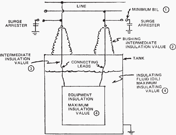

    Hybrid HVDC Breaker Construction

    The hybrid HVDC breaker consists of an additional branch, a bypass formed by a semiconductor-based load commutation switch in series with a fast mechanical disconnector.

    The main semiconductor-based HVDC breaker is separated into several sections with individual arrester banks dimensioned for full voltage and current breaking capability, whereas the load commutation  switch matches lower voltage and energy capability.

    After fault clearance, a disconnecting circuit  breaker interrupts the residual current and isolates the faulty line from the HVDC grid to protect the  arrester banks of the hybrid HVDC breaker from thermal overload.

    Hybrid HVDC breaker main components

    Figure 1 - Hybrid HVDC breaker main components


    During normal operation the current will only flow through the bypass, and the current in the main breaker is zero.

    When an HVDC fault occurs, the load commutation switch immediately commutates  the current to the main HVDC breaker and the fast disconnector opens. With the mechanical switch in  open position, the main HVDC breaker breaks the current.

    The mechanical switch isolates the load commutation switch from the primary voltage across the main HVDC breaker during current breaking.

    Thus, the required voltage rating of the load commutation switch is significantly reduced.

    A successful commutation of the line current into the main HVDC breaker path requires a voltage rating of the load commutation switch exceeding the on-state voltage of the main HVDC breaker, which is typically in the kV range for a 320 kV HVDC breaker.

    This result in typical on-state voltages of the load commutation switch is in the range of several volts only.

    The transfer losses of the hybrid HVDC breaker concept are thus significantly reduced to a percentage of the losses incurred by a pure semiconductor breaker.

    The mechanical switch opens at zero current with low voltage stress, and can thus be realized as a disconnector with a lightweight contact system. The fast disconnector will be exposed to the maximum pole-to-pole voltage defined by the protective level of the arrester banks after first being in open position while the main HVDC breaker opens.

    Thomson drives result in fast opening times and compact disconnector design using SF6 as insulating media.

    Go to Content ↑


    Proactive control

    Proactive control of the hybrid HVDC breaker allows it to compensate for the time delay of the fast disconnector, if the opening time of the disconnector is less than the time required for selective protection.

    Proactive control of hybrid HVDC breaker

    Figure 2 - Proactive control of hybrid HVDC breaker. LCS denotes load commutation switch


    As shown in Figure 2, proactive current commutation is initiated by the hybrid HVDC  breaker’s built-in overcurrent protection as soon as the HVDC line current exceeds a certain overcurrent level. The main HVDC breaker delays current breaking until a trip signal of the selected protection is received or the faulty line current is close to the maximum breaking current capability of  the main HVDC breaker.

    To extend the time before the self-protection function of the main HVDC breaker trips the hybrid HVDC breaker, the main HVDC breaker may operate in current limitation mode prior to current breaking.

    The main HVDC breaker controls the voltage drop across the HVDC reactor to zero to prevent a further rise in the line current.

    Pulse mode operation of the main HVDC breaker or sectionalizing the main HVDC breaker as shown in Figure 2 will allow adapting the voltage across the main HVDC breaker to the instantaneous HVDC voltage level of the HVDC grid.

    The maximum duration of the current limiting mode depends on the energy  dissipation capability of the arrester banks.

    On-line supervision allowing maintenance on demand is achieved by scheduled current transfer of the line current from the bypass into the main HVDC current breaker during normal operation, without disturbing or interrupting the power transfer in the HVDC grid.

    Fast backup protection similar to pure semiconductor breakers is possible for hybrid HVDC breakers applied to HVDC switchyards.

    Due to the proactive mode, over-currents in the line or superior switchyard protection will activate the current transfer from the bypass into the main HVDC breaker or possible backup breakers prior to the trip signal of the backup protection.

    In the case of a breaker failure, the backup breakers are activated almost instantaneously, typically within less than 0.2 ms. This will avoid major disturbances in the HVDC grid, and keep the required current-breaking capability of the backup breaker at reasonable values. If not utilized for backup protection, the hybrid HVDC breakers automatically return to normal operation mode after the fault is cleared.

    Go to Content ↑


    Prototype Design Of The Hybrid HVDC Breaker

    The hybrid HVDC breaker is designed to achieve a current breaking capability of 9.0 kA in an HVDC grid with rated voltage of 320 kV and rated HVDC transmission current of 2 kA. The maximum current breaking capability is independent of the current rating and depends on the design of the main HVDC breaker only.

    The fast disconnector and main HVDC breaker are designed for switching voltages exceeding 1.5 p.u. in consideration of fast voltage transients during current breaking.

    Design of 80kV main HVDC breaker cell

    Figure 3 - Design of 80kV main HVDC breaker cell


    The main HVDC breaker consists of several HVDC breaker cells with individual arrester banks limiting the maximum voltage across each cell to a specific level during current breaking. Each HVDC breaker cell contains four HVDC breaker stacks as shown in Figure 3.

    Two stacks are required to break the current in either current direction.

    Each stack is composed of up to 20 series connected IGBT (insulated gate bipolar transistor) HVDC breaker positions.

    Due to the large di/dt stress during current breaking, a mechanical design with low stray inductance is required.

    Application of press pack IGBTs with 4.5 kV voltage rating [6] enables a compact stack design and ensures a stable short circuit failure mode in case of individual component failure. Individual RCD snubbers across each IGBT position ensure equal voltage distribution during current breaking.

    Optically powered gate units enable operation of the IGBT HVDC breaker independent of current and voltage conditions in the HVDC grid. A cooling system is not required for the IGBT stacks, since the main HVDC breaker cells are not exposed to the line current during normal operation.

    For the design of the auxiliary HVDC breaker, one IGBT HVDC breaker position for each current direction is sufficient to fulfill the requirements of the voltage rating.

    Parallel connection of IGBT modules increases the rated current of the hybrid HVDC breaker. Series connected, redundant IGBT HVDC breaker positions improve the reliability of the auxiliary HVDC breaker.

    A matrix of 3×3 IGBT positions for each current direction is chosen for the present design. Since the auxiliary HVDC breaker is continuously exposed to the line current, a cooling system is required.

    Besides water cooling, air-forced cooling can be applied, due to relatively low losses in the range of several tens of kW only.

    Go to Content ↑

    Comparison

    Existing mechanical HVDC breakers are capable of interrupting HVDC currents within several tens of milliseconds, but this is too slow to fulfill the requirements of a reliable HVDC grid.

    HVDC breakers based on semiconductors can easily overcome the limitations of operating speed, but generate large transfer losses, typically in the range of 30 percent of the losses of a voltage source converter station.

    To overcome these obstacles, ABB has developed a hybrid HVDC breaker described above.

    The hybrid design has negligible conduction losses, while preserving ultra-fast current interruption capability.

    Go to Content ↑

    Resource: ABB Grid Systems, Technical Paper Nov’2012: The Hybrid HVDC Breaker – An innovation breakthrough enabling reliable HVDC grids

    Using Protective Relay For Fighting Against Faults

    $
    0
    0
    Using Protective Relay For Fighting Against Faults

    Using Protective Relay For Fighting Against Faults

    Content

    1. Introduction to Protective Relay
    2. Working Principle of Protective Scheme
    3. What is Relay?
    4. Functions of Protective Relay
    5. Desirable qualities of protective relaying
    6. Terminology of protective relay
    7. History of Protective Relay
    8. Types of Relays
    9. Types of Relay based on Relay Operation Mechanism
    10. Protective relay testing: Test relays of all generations (VIDEO)

    Introduction to Protective Relay

    Protective relay works in the way of sensing and control devices to accomplish its function. Under normal power system operation, a protective relay remains idle and serves no active function.

    But when fault or undesirable condition arrives Protective Relay must be operated and function correctly.

    A Power System consists of various electrical components like Generator, transformers, transmission lines, isolators, circuit breakers, bus bars, cables, relays, instrument transformers, distribution feeders, and various types of loads.

    Faults may occur in any part of power system as a short circuit and earth fault. Fault may be Single Line to Ground, Double Line to Ground, Line to Line, three phase short circuit etc. This results in flow of heavy fault current through the system.

    Fault level also depends on the fault impedance which depends on the location of fault referred from the source side. To calculate fault level at various points in the power system, fault analysis is necessary.

    The protection system operates and isolates the faulty section. The operation of the protection system should be fast and selective i.e. it should isolate only the faulty section in the shortest possible time causing minimum disturbance to the system. Also, if main protection fails to operate, there should be a backup protection for which proper relay co-ordination is necessary.

    Failure of a protective relay can result in devastating equipment damage and prolonged downtime.

    Go to Content ↑


    Working Principle of Protective Scheme

    Protective relaying senses the abnormal condition in a part of power system and gives an alarm or isolates that part from healthy system. Protective relaying is a team work of CT, PT, protective relays, time delay relays, trip circuits, circuit breakers etc.

    Protective relaying plays an important role in minimizing the faults and also in minimizing the damage in the event of faults.

    Basic connections of circuit breaker control for the opening operation

    Basic connections of circuit breaker control for the opening operation


    Figure above shows basic connections of circuit breaker control for the opening operation. The protected circuit X is shown by dashed line. When a fault occurs in the protected circuit the relay connected to CT and PT actuates and closes its contacts.

    Current flows from battery in the trip circuit. As the trip coil of circuit breaker is energized, the circuit breaker operating mechanism is actuated and it operates for the opening operation.

    Thus the fault is sensed and the trip circuit is actuated by the relay and the faulty part is isolated.

    Go to Content ↑


    What is Relay?

    A relay is automatic device which senses an abnormal condition of electrical circuit and closes its contacts.

    These contacts in turns close and complete the circuit breaker trip coil circuit hence make the circuit breaker tripped for disconnecting the faulty portion of the electrical circuit from rest of the healthy circuit.

    Go to Content ↑


    Functions of Protective Relay

    These are the main functions of protective relay:

    1. To sound an alarm or to close the trip circuit of a circuit breaker so as to disconnect Faulty Section.
    2. To disconnect the abnormally operating part so as to prevent subsequent faults. For e.g. Overload protection of a machine not only protects the machine but also prevents Insulation failure.
    3. To isolate or disconnect faulted circuits or equipment quickly from the remainder of the system so the system can continue to function and to minimize the damage to the faulty part. For example – If machine is disconnected immediately after a winding fault, only a few coils may need replacement. But if the fault is sustained, the entire winding may get damaged and machine may be beyond repairs.
    4. To localize the effect of fault by disconnecting the faulty part from healthy part, causing   least disturbance to the healthy system.
    5. To disconnect the faulty part quickly so as to improve system stability, service continuity and system performance. Transient stability can be improved by means of improved   protective relaying.
    6. To minimize hazards to personnel.

    Go to Content ↑

    Desirable Qualities of Protective Relaying

    1. Selectivity,
    2. Discrimination
    3. Stability
    4. Sensitivity,
    5. Power consumption
    6. System Security
    7. Reliability
    8. Adequateness
    9. Speed & Time

    Go to Content ↑


    Terminology of protective relay

    Pickup level of actuating signal: The value of actuating quantity (voltage or current) which is on threshold above which the relay initiates to be operated. If the value of actuating quantity is increased, the electromagnetic effect of the relay coil is increased and above a certain level of actuating quantity the moving mechanism of the relay just starts to move.

    Reset level: The value of current or voltage below which a relay opens its contacts and comes in original position.

    Operating Time of Relay: Just after exceeding pickup level of actuating quantity the moving mechanism (for example rotating disc) of relay starts moving and it ultimately close the relay contacts at the end of its journey. The time which elapses between the instant when actuating quantity exceeds the pickup value to the instant when the relay contacts close.

    Reset time of Relay: The time which elapses between the instant when the actuating quantity becomes less than the reset value to the instant when the relay contacts returns to its normal position.

    Reach of Relay: A distance relay operates whenever the distance seen by the relay is less than the pre-specified impedance. The actuating impedance in the relay is the function of distance in a distance protection relay. This impedance or corresponding distance is called reach of the relay.

    Go to Content ↑


    History of Protective Relay

    The evolution of protective relays begins with the electromechanical relays. Over the past decade it upgraded from electromechanical to solid state technologies to predominate use of microprocessors and microcontrollers.

    The timeline of the development of protective relays is shown below:

    1900 to 19631963 to 19721972 to 19801980 to 1990
    Electromechanical RelayStatic RelayDigital RelayNumerical Relay
    1925=Single Disc Type Relay (Single Input)1963=Static Relay  (All Purpose)1980=Digital Type Relay (All Purpose)1990=Numerical Type Relay (All Purpose)
    1961=Single Cup Type Relay (Impedance Relay)1972=Static Relay with self checking           (All Purpose)

    Go to Content ↑


    Types of Relays

    Types of protection relays are mainly:

    A. Based on Characteristic:

    1. Definite time Relays.
    2. Inverse definite minimum time Relays (IDMT)
    3. Instantaneous Relays
    4. IDMT with Instantaneous.
    5. Stepped Characteristic
    6. Programmed Switches
    7. Voltage restraint over current relay

    B. Based on logic:

    1. Differential
    2. Unbalance
    3. Neutral Displacement
    4. Directional
    5. Restricted Earth Fault
    6. Over Fluxing
    7. Distance Schemes
    8. Bus bar Protection
    9. Reverse Power Relays
    10. Loss of excitation
    11. Negative Phase Sequence Relays etc.

    C. Based on Actuating parameter:

    1. Current Relays
    2. Voltage Relays
    3. Frequency Relays
    4. Power Relays etc.

    D. Based on Operation Mechanism:

    1. Electro Magnetic Relay
    2. Static Relay
    ……• Analog Relay
    ……• Digital Relay
    ……• Numerical /Microprocessor Relay
    3. Mechanical relay

    • Thermal
      • OT Trip (Oil Temperature Trip)
      • WT Trip (Winding Temperature Trip)
      • Bearing Temp Trip etc.
    • Float Type
      • Buchholz
      • OSR
      • PRV
      • Water level Controls etc.
    • Pressure Switches
    • Mechanical Interlocks
    • Pole discrepancy Relay

    E. Based on Applications

    1. Primary Relays
    2. Backup Relays

    Go to Content ↑


    Types of Relay based on Relay Operation Mechanism

    1. Electromagnetic Relay

    Electromagnetic relays are further categorized under two following categories.

    1.1 Electromagnetic Attraction Relay
    This Relay works on Electromagnetic Attraction Principle

    1.2 Electromagnetic Induction Relay
    This Relay works on Electromagnetic Induction Principle


    2. Solid State (Static) Relay

    Solid-state (and static) relays are further categorized under following designations:

    2.1 Analog Relay
    In Analog relays are measured quantities are converted into lower voltage but similar signals, which are then combined or compared directly to reference values in level detectors to produce the desired output.

    2.2 Digital Relay
    In Digital relays measured ac quantities are manipulated in analogue form and subsequently converted into square-wave (binary) voltages. Logic circuits or microprocessors compare the phase relationships of the square waves to make a trip decision.

    2.3 Numerical Relay
    In Numerical relays measured ac quantities are sequentially sampled and converted into numeric data form. A microprocessor performs mathematical and/or logical operations on the data to make trip decisions.

    Go to Content ↑


    Protective relay testing: Test relays of all generations (VIDEO)

    Cant see this video? Click here to watch it on Youtube.

    Go to Content ↑


    References

    • Handbook of Switchgear –Bhel
    • Digital/Numerical Relays -T.S.M. Rao

    The Good Old Electromechanical Protective Relay

    $
    0
    0
    The Good Old Electromechanical Protective Relay

    The Good Old Electromechanical Protective Relay (on photo: GE's first innovation is this induction disk electromechanical protection relay. They've come a long way since 1910 - by MEDI Ontario @ Flickr)

    History of Relay

    This is the first generation oldest relaying system and they have been in use for many years. They have earned a well-deserved reputation for accuracy, dependability, and reliability.

    There are two basic types of operating mechanisms:

    1. Electromagnetic-attraction relay and
    2. Electromagnetic-induction relay

    Measuring Principles

    The electromechanical protective relay converts the voltages and currents to magnetic and electric forces and torques that press against spring tensions in the relay.

    The tension of the spring and taps on the electromagnetic coils in the relay are the main processes by which a user sets in a relay.


    Function of Relay

    These relays are usually instantaneous in action, with no intentional time delay, closing as soon after pickup as the mechanical motion permits. We can add time delay by means of a bellows, dashpot, or a clockwork escapement mechanism.

    However, the timing accuracy is considerably less precise than that of induction type relays.

    As such, users seldom choose these relays with time delay in switchgear applications.

    Electromechanical Relays can operate with either AC or DC on the coils. Therefore, the DC component of an asymmetrical fault definitely affects these relays using this principle.

    Most relays come enclosed in a semi flush-mounting draw out case. Installers typically install relays usually on the door of the switchgear cubicle. They bring sensor and control wiring to connections on the case. The relay inserts into the case and connects by means of small switches or a bridging plug, depending on the manufacturer.

    As such, we can disconnect and withdraw it from the case without disturbing the wiring. When the relay is disconnected, the current transformer (CT) connections in the case are automatically shorted to short circuit the CT secondary winding and protect the CT from over voltage and damage.


    Operation of Electromagnetic-attraction Relay

    Figure shows a typical electromechanical relay. An input voltage is applied to the coil mechanism. The input voltage magnetizes the core which pulls the arm towards it. This action causes the output contacts to touch, closing the load circuit.

    When the input voltage is removed, the spring lever will push the contacts away from each other, breaking the load circuit connection.

    Operation of Electromagnetic-attraction Relay

    Operation of Electromagnetic-attraction Relay

    Operation of Electromagnetic-Induction Relay

    Induction relays are available in many variations to provide accurate pickup and time-current responses for a wide range of simple or complex system.

    They are actually like induction motors. On the relay, the moving element (rotor) is usually a metal disk, although sometimes it’s a metal cylinder or cup. The stationary part (stator) is one or more integral electromagnets, with current or potential coils inducing currents in the disk, causing it to rotate.

    Until the rotational forces are great enough to turn the disk and bring its moving contact against the stationary contact, a spring restrains the disk motion.

    Induction-type overcurrent relay

    Close-up of an induction-type overcurrent unit, showing the disc rotor and drag magnet


    This closes the circuit the relay is controlling. The greater the sensed fault, the greater the current in the coils, and the faster the disk rotates.

    A calibrated adjustment called the time dial sets the spacing between the moving and stationary contacts; this varies the operating time of the relay from fast (contacts only slightly open) to slow (contacts nearly a full disk revolution apart).

    Reset action begins upon removing the rotational force, either by closing the relay contact that trips a breaker or by otherwise removing the malfunction the relay is sensing. The restraining spring resets the disk to its original position. The time required to reset depends on the type of relay and the time-dial setting (contact spacing).

    Most electromechanical Relays are typically rated for minimum input to output isolation voltages of 1500 to 2000 VAC.

    Limitations of Electromagnetic relays

    1. Low speed of operation.
    2. Change in characteristics over a period due to ageing effect.
    3. Component failure leading to relay failure.
    4. Relay is Bulky: Because there are internal mechanical components with physical dimension restraints, the package size of an electromechanical Relay can limit the size of a PCB design Excessive power consumption.
    5. Imposes high burden on CT
    6. No fault data available except phase indication.
    7. Inherent in its design, the Electromechanical Relay must make mechanical contacts in order to switch a load. At the point of these contacts, oxidation breakdown occurs over extended life cycling (typically 106 operations), and the relay will need to be replaced.
    8. When an electromechanical Relay is activated, bounce occurs at the contact site. Bounce creates a window of time where the load circuit is flickering between open and closed, a condition which may need to be considered in load design.
    9. Isolation voltage is another area where Electromechanical Relays are limited.

    References

    • Handbook of Switchgear –Bhel
    • Digital/Numerical Relays -T.S.M. Rao

    The Solid State Relay (Static Relay) Overview

    $
    0
    0
    The Solid State Relay (Static Relay) Overview

    The Solid State Relay (Static Relay) Overview (on photo: Basler Electric BE1-27 Solid State Protective Relay, Over/Under Voltage)

    History of Relay

    The static relay is the next generation relay after electromechanical type.The Solid Static relays was first introduced in 1960’s. The term ‘static’ implies that the relay has no moving mechanical parts in it.

    Compared to the Electromechanical Relay, the Solid Static relay has longer life-span, decreased noise when operates and faster respond speed.

    However, it is not as robust as the Electromechanical Relay.

    Static relays were manufactured as semiconductor devices which incorporate transistors, ICs, capacitors, small microprocessors etc.

    The static relays have been designed to replace almost all the functions which were being achieved earlier by electromechanical relays.


    Measuring principles

    The working principle of the Solid Static relays is similar to that of the Electromechanical Relay which means the Solid Static relays can perform tasks that the Electromechanical Relay can perform.

    The Solid Static relays use analogue electronic devices instead of magnetic coils and mechanical components to create the relay characteristics. The measurement is carried out by static circuits consisting of comparators, level detectors, filter etc while in a conventional electromagnetic relay it is done by comparing operating torque (or force) with restraining torque (or force). The relaying quantity such as voltage/current is rectified and measured.

    When the quantity under measurement attains certain well-defined value, the output device is triggered and thereby the circuit breaker trip circuit is energized.

    In a solid state relay, the incoming voltage and current waveforms are monitored by analog circuits, not recorded or digitized. The analog values are compared to settings made by the user via potentiometers in the relay, and in some case, taps on transformers.

    In some solid state relays, a simple microprocessor does some of the relay logic, but the logic is fixed and simple.

    For instance, in some time over current solid state relays, the incoming AC current is first converted into a small signal AC value, and then the AC is fed into a rectifier and filter that converts the AC to a DC value proportionate to the AC waveform. An op-amp and comparator is used to create a DC that rises when a trip point is reached. Then a relatively simple microprocessor does a slow speed A/D conversion of the DC signal, integrates the results to create the time-over current curve response, and trips when the integration rises above a set point.

    Though this relay has a microprocessor, it lacks the attributes of a digital/numeric relay, and hence the term “microprocessor relay” is not a clear term.


    Function of Relay

    Early versions used discrete devices such as transistors and diodes in conjunction with resistors, capacitors, inductors, etc., but advances in electronics enabled the use of linear and digital integrated circuits in later versions for signal processing and implementation of logic functions.

    While basic circuits may be common to a number of relays, the packaging was still essentially restricted to a single protection function per case, while complex functions required several cases of hardware suitably interconnected.

    Basler Electric BE1-27 Solid State Protective Relay

    Basler Electric BE1-27 Solid State Protective Relay, Over/Under Voltage


    User programming was restricted to the basic functions of adjustment of relay characteristic curves.

    Therefore it can be viewed in simple terms as an analogue electronic replacement for electromechanical relays, with some additional flexibility in settings and some saving in space requirements.

    In some cases, relay burden is reduced, making for reduced CT/VT output requirements. In a static relay there is no armature or other moving element and response is developed by electronic, magnetic or other components without mechanical motion.

    A relay using combination of both static and electromagnetic units is also called a static relay provided that static units accomplish the response. Additional electromechanical relay units may be employed in output stage as auxiliary relays. A protective system is formed by static relays and electromechanical auxiliary relays.

    The performance of static relay is better than electromagnetic relays as they are fast acting and accuracy of measurement is better than electromagnetic relay.

    The constraint in static relay is limited function/features.

    In the last decade, some microprocessors were introduced in this relay to achieve the functions like:

    1. Fuse failure features
    2. Self check feature
    3. Dead Pole detection and
    4. Carrier aided protection features

    Operation of Relay

    The essential components of static relays are shown in figure below. The output of CT and PT are not suitable for static components so they are brought down to suitable level by auxiliary CT and PT. Then auxiliary CT output is given to rectifier.

    Rectifier rectifies the relaying quantity i.e., the output from a CT or PT or a Transducer.

    Solid state relay - Operation

    Solid state relay - Operation


    The rectified output is supplied to a measuring unit comprising of comparators, level detectors, filters, logic circuits.

    The output is actuated when the dynamic input (i.e., the relaying quantity) attains the threshold value. This output of the measuring unit is amplified by amplifier and fed to the output unit device, which is usually an electromagnetic one.

    The output unit energizes the trip coil only when relay operates.


     Advantages of Solid State Relay

    • Static Relay burden is less than Electromagnetic type of relays. Hence error is less.
    • Low Weight
    • Required Less Space which results in panel space saving.
    • Arc less switching
    • No acoustical noise.
    • Multi-function integration.
    • Fast response.
    • Long life (High Reliability): more than 109 operations
    • High Range of Setting compared to electromechanical Relay
    • More Accurate compared to electromechanical Relay
    • Low Electromagnetic Interference.
    • Less power consumption.
    • Shock and vibration resistant
    • No contact bounce
    • Microprocessor compatible.
    • Isolation of Voltage

    No moving parts: There are no moving parts to wear out or arcing contacts to deteriorate that are often the primary cause of failure with an Electro Mechanical Relay.

    No mechanical contact bounce or arcing: A solid-state relay doesn’t depend on mechanical forces or moving contacts for its operation but performs electronically. Thus, timing is very accurate even for currents as low as the pickup value. There is no mechanical contact bounce or arcing, and reset times are extremely short.

    Low input signal levels: Ideal for Telecommunication or microprocessor control industries. Solid state relays are fast becoming the better choice in many applications, especially throughout the telecommunication and microprocessor control industries.

    Cost Issues: In the past, there has been a rather large gap between the price of an electromechanical relay and the price of a solid state relay. With continual advancement in manufacturing technology, this gap has been reduced dramatically making the advantages of solid state technology accessible to a growing number of design engineers.

    Limitations of static relays

    • Auxiliary voltage requirement for Relay Operation.
    • Static relays are sensitive to voltage transients which are caused by operation of breaker and isolator in the primary circuit of CTs and PTs.
    • Serious over voltage is also caused by breaking of control circuit, relay contacts etc. Such voltage spikes of small duration can damage the semiconductor components and also cause mal operation of relays.
    • Temperature dependence of static relays: The characteristics of semiconductor devices are affected by ambient temperature.
    • Highly sophisticated isolation and filter circuits are required to be built into the relay design to take care of electromagnetic interference and transient switching disturbances in the power system.
    • Highly reliable power supply circuits are required.
    • Effect of environmental conditions like humidity, high ambient temperature, dust accumulation on PCB leading to tracking.
    • The component failure.
    • Non availability of fault data.
    • Characteristic variations with passage of time.

    References

    • Handbook of Switchgear –Bhel
    • Digital/Numerical Relays -T.S.M. Rao
    Viewing all 1475 articles
    Browse latest View live