Quantcast
Channel: EEP – Electrical Engineering Portal
Viewing all 1474 articles
Browse latest View live

Application of Circuit Breakers in IT Networks

$
0
0
Application of Circuit Breakers in IT Networks

Application of Circuit Breakers in IT Networks (on photo LV switchboard by MaTech Magyar Technologiai Kft.)

Introduction

IT supplies are used to prevent that a ground fault leads to immediate disconnection of the affected circuit like in a grounded system. Although a first ground fault results in a displacement of the potential of the entire supply, continued operation is still temporarily possible.

Special ground fault monitoring equipment reports any ground faults and hence makes it possible to quickly rectify the fault – often without disruption to the operation of the plant.

The situation is similar in supplies with high impedance grounding.

If however a second ground fault occurs in another phase, there is a short-circuit that must be immediately cleared by the short-circuit protective device. The voltage to be switched off varies depending on the locations of the short-circuits (Figure 1).

This results in different voltage levels to be switched off by the short-circuit protective device and in the case of circuit breakers to different required breaking capacities.
Double ground faults on the load side of the circuit breakers do not cause increased stress.

Figure 1 - Double ground faults on the load side of the circuit breakers do not cause increased stress.


If, however, there is one ground fault on the supply side and the other on the load-side, a significantly higher breaking capacity is required because of the increased voltage load.

If both short-circuits occur on the load-side of the circuit breaker, the breaking work is shared between two contacts and the required breaking capacity corresponds to the normal 3-phase values.

If the location of one short-circuit is on the supply-side of the circuit breaker and the second short-circuit on the load-side, then one contact only of the circuit breaker has to perform the total breaking work and this at phase-to-phase voltage. In this case, the significantly lower single pole breaking capacity of the circuit breaker at the phase-to-phase voltage is critical. If the values cannot be obtained from the device documents, an inquiry should be made. If the short-circuit current at the installation site exceeds the single pole switching capacity of the circuit breaker, then a back-up fuse is required.

For three-pole short-circuits there is no difference between IT supplies and other supply types.

The ultimate short-circuit breaking capacity Icuand the service short-circuit breaking capacity Ics continue to apply. Circuit breakers under IEC 60947-2 are suitable for use in IT supplies, if they are not marked with the symbol Symbol not for IT. Testing is in accordance with Annex H.

Resource: Allen Bradley – Low Voltage Switchgear and Controlgear


Aluminium and its Alloys used in Electrical Engineering

$
0
0
Aluminium and its Alloys used in Electrical Engineering

Aluminium and its Alloys used in Electrical Engineering (photo by Daniel Richert @ Flickr)

Introduction

Aluminium has been used for many years as a conductor material in almost all branches of electrical engineering. In addition to the pure aluminium, several its alloys are also excellent conductors, combining structural strength with an quite acceptable conductivity.

Aluminum is used everywhere in the electrical industry. Motors are wound with it, high voltage lines are  made with it, and the drop from the power line to your house’s circuit breaker box is probably aluminum.

The material is lighter than copper (about one third the density) and therefore easier to handle; it is also cheaper.

Another advantage is that its price is not subject to wide fluctuations as is copper. There was a sharp increase in the price of copper worldwide in the 1960s and 1970s. This led to many instances of aluminium being used in situations where copper had previously been the norm.

In a few applications, for example domestic wiring and transformer foil-windings identified below, aluminium proved to be less suitable than was initially hoped, so that in the late 1990s there has been some return to copper and the use of aluminium has tended to be restricted to those applications for which it is clearly superior.

There are two groups of British Standard Specifications for aluminium:

  1. One covering aluminium for electrical purposes, which relates to high purity aluminium with emphasis on electrical properties, and
  2. The second concerning aluminium for general engineering.
Aluminium for electrical purposes covers grades with conductivities between 55% and 61% International Annealed Copper Standard (IACS) and includes pure aluminium.

The following are the relevant British Standards:

  • BS 215 Part 1: (IEC 207) Aluminium stranded conductors for overhead power transmission purposes.
  • BS 215 Part 2: (IEC 209) Aluminium conductors, steel-reinforced for overhead power transmission purposes.
  • BS 2627. Wrought aluminium for electrical purposes – wire.
  • BS 2897. Wrought aluminium for electrical purposes – strip with drawn or rolled edges.
  • BS 2898. Wrought aluminium for electrical purposes – bars, extruded round tubes and sections.
  • BS 3242. (IEC 208) Aluminium alloy stranded conductors for overhead power transmission.
  • BS 3988. Wrought aluminium for electrical purposes – solid conductors for insulated cables.
  • BS 6360. Specifications for conductors in insulated cables and cords.

This group of specifications include grade 1350 (formerly 1E) pure aluminium with a conductivity of 61% IACS and grade 6101A (formerly 91E) which is a heat treatable alloy with moderate strength and a conductivity of 55% IACS.

Aluminium for general engineering uses includes grades with conductivities as low as 30% IACS, but with high structural strength, up to 60% of that of steel, with greater emphasis on mechanical properties.

This is covered by the following British Standards:

  • BS 1471 Wrought aluminium and aluminium alloys – drawn tube.
  • BS 1472 Wrought aluminium and aluminium alloys – forging stock and forgings.
  • BS 1473 Wrought aluminium and aluminium alloys – rivet, bolt and screw stock.
  • BS 1474 Wrought aluminium and aluminium alloys – bars, extruded round tube and sections.
  • BS 1475 Wrought aluminium and aluminium alloys – wire.
  • BS 1490 Aluminium ingots and castings (based on but not identical to ISO 3522).
  • BS EN 485 Aluminium and aluminium alloys – sheet, strip and plate.

This group of specifications includes grade 1050A (formerly 1B) with a conductivity of 61.6 IACS, grade 1080A (formerly 1A) also with a conductivity of 61.6 IACS, and grade 1200 (formerly 1C) with a conductivity of 59.5% IACS. These grades are generally used in sheet form, up to 10mm thick, or plate, over 10mm thick.

Further information on aluminium grades and specifications can be obtained from the Aluminium Federation.


Aluminium Applications

Busbars

Aluminium has been used for busbars for more than 60 years and from 1960 onwards is increasingly being used for a whole range of busbar applications due to its light weight and durability.

Tubular aluminium is used exclusively for grid substation busbars at 275kV and 400kV (Gas-Insulated Transmission Line – GIL) and is increasingly being used at 132kV for substation refurbishments and redevelopments.

Aluminium is used in large industrial plants such as smelters and electrochemical plants because of the availability of large sections of cast bars (up to 600mm × 150mm). Aluminium is also used in switchgear and rising main systems because of its lighter weight compared with copper.

A major problem with aluminium is the rapidity with which it oxidizes when the surface is prepared for bolted jointing. Much research was carried out by the former CEGB into the problem especially with the heavy currents which arise between a generator and its associated step-up transformer. This resulted in significant improvements in jointing techniques.

Bolted joints in aluminium busbars which are subject to frequent dismantling are frequently electroplated using silver or tin.


Cable

Aluminium is extensively employed as the conductors over 16mm2 cross-sectional area for power cables up to 66kV. Aluminium is not normally found in domestic wiring installations because of the specialized jointing and termination techniques needed to ensure longevity of trouble-free service.


Overhead lines

The a.c.s.r. (aluminium conductor steel reinforced) overhead line conductors are used worldwide for power distribution systems.

A.c.a.r. (aluminium conductor aluminium alloy wire reinforced) have increasingly been used since 1960 because of the elimination of the risk of bi-metallic corrosion and improved conductivity for a given cross-section. A.c.a.r. catenary conductors for supporting the contact wire are also finding favour with railway authorities for overhead electrification schemes because of their lower weight and the reduced risk of theft in comparison with copper.


Motors

Cage rotors for induction motors often employ aluminium bars. Casings are also made from the material as are fans used for motor cooling purposes.


Foil windings

Aluminium is the norm for the windings of capacitors from the smallest types used in lighting fittings to large power capacitors.

Foil windings are suitable for some transformers, reactors and solenoids. Foil thicknesses range from 0.040 mm to 1.20 mm in 34 steps. A better space factor than for a wire wound copper coil is obtained, the aluminium conductor occupying some 90% of the space as against 60% for copper wire.

Heating and cooling are aided by the better space factor and the smaller amount of insulation needed for foil wound coils. Rapid radial heat transfer ensures an even temperature gradient.

The disadvantage of aluminium is its poorer mechanical strength, particularly from the viewpoint of making winding end connections.

The tendency, therefore has been to turn to the use of copper foil for air insulated low voltage windings.

Aluminium foil is, however, almost exclusively used for the HV windings of cast resin insulated transformers as it has a thermal expansion coefficient closer to that of the resin encapsulation material than does copper which thus reduces the thermal stresses arising under load.


Constants and physical properties of very high purity aluminium

DescriptionValue
Atomic number13
Atomic volume10cm3/g-atom
Atomic weight26.98
Valency3
Crystal structurefcc
Interatomic distance (co-ordination number 12)2.68 kX
Heat of combustion200 k cal/g-atom
Latent heat of fusion94.6 cal/g
Melting point660.2 °C
Boiling point2480 °C
Vapour pressure at 1200°C1 × 10-2 mm Hg
Mean specific heat (0–100°C)0.219 cal/g°C
Thermal conductivity (0–100°C)0.57 cal/cm s°C
Temperature coefficient of linear expansion (0–100°C)23.5 × 10⁻⁶ per °C
Electrical resistivity at 20°C2.69 microhm cm
Temperature coefficient of resistance (0–100°C)4.2 × 10⁻³ per °C
Electrochemical equivalent3.348 × 10-1 g/Ah
Density at 20°C2.6898 g/cm3
Modulus of elasticity68.3 kN/mm2
Modulus of torsion25.5 kN/mm2
Poisson’s ratio0.34

Heating elements

Aluminium foil heating elements have been developed but are not widely used at present. Applications include foil film wallpapercuring concrete and possibly soil warming.


Heatsinks

High thermal conductivity of aluminium and ease of extruding or casting into solid or hollow shapes with integral fins makes the material ideal for heatsinks.

Semiconductor devices and transformer tanks illustrate the wide diversity of applications in this field. Its light weight makes it ideal for pole-mounted transformer tanks and it has the added advantage that the material does not react with transformer oil to form a sludge.

Resource: Newnes Electrical Pocket Book – E.A. Reeves; Martin J. Heathcote
(get this book at Amazon)

Few Words About Synchronous Machines

$
0
0
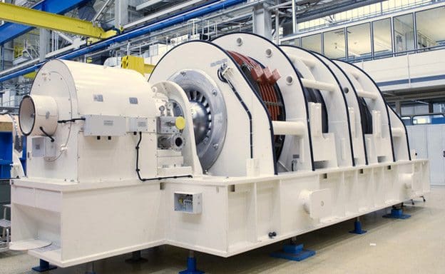
Gearless synchronous generator for wind power plants developed by SIEMENS

Figure 1 - Gearless synchronous generator for wind power plants developed by SIEMENS

Introduction to Synchronous Machine

There are two main types of synchronous machine: cylindrical rotor and salient pole.

In general, the former is confined to 2 and 4 pole turbine generators, while salient pole types are built with 4 poles upwards and include most classes of duty. Both classes of machine are similar in so far that each has a stator carrying a three-phase winding distributed over its inner periphery.

Within the stator bore is carried the rotor which is magnetised by a winding carrying d.c. current.

The essential difference between the two classes of machine lies in the rotor construction.

The cylindrical rotor type has a uniformly cylindrical rotor that carries its excitation winding distributed over a number of slots around its periphery. This construction is unsuited to multi-polar machines but it is very sound mechanically.

Hence it is particularly well adapted for the highest speed electrical machines and is universally employed for two pole units, plus some four pole units.

The salient pole type has poles that are physically separate, each carrying a concentrated excitation winding. This type of construction is in many ways complementary to that of the cylindrical rotor and is employed in machines having 4 poles or more. Except in special cases its use is exclusive in machines having more than 6 poles.

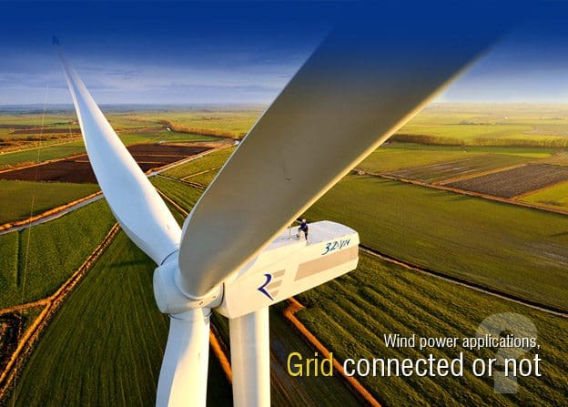
Figure 1 above illustrates a gearless synchronous generator for wind power plants developed by SIEMENS installed in a power plant. The unit, which has an extremely high efficiency rating of 98%, uses permanent magnets to convert wind energy from the rotor into electricity. The gearless generator avoids losses due to friction and heat and starts to operate even at low winds or in brief gusts. Because of this innovative design the generator doesn’t need gear oil and has fewer mechanical parts subject to wear and tear, which means less downtime.

Two and four pole generators are most often used in applications where steam or gas turbines are used as the driver. This is because the steam turbine tends to be suited to high rotational speeds.

Four pole steam turbine generators are most often found in nuclear power stations as the relative wetness of the steam makes the high rotational speed of a two-pole design unsuitable.

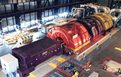
SIEMENS's 2 pole generators customized for the use on gas and steam turbines

SIEMENS's 2 pole generators customized for the use on gas and steam turbines


Large 4-Pole Generators - ALSTOM Power

Large 4-Pole Generators designed by ALSTOM Power for maximum reliability, availability and maintainability. The design also takes into account optimum erection, commissioning, testing and plant layout


Most generators with gas turbine drivers are four pole machines to obtain enhanced mechanical strength in the rotor- since a gearbox is often used to couple the power turbine to the generator, the choice of synchronous speed of the generator is not subject to the same constraints as with steam turbines.

Generators with diesel engine drivers are invariably of four or more pole design, to match the running speed of the driver without using a gearbox. Four-stroke diesel engines usually have a higher running speed than two-stroke engines, so generators having four or six poles are most common.

Two-stroke diesel engines are often derivatives of marine designs with relatively large outputs (circa 30MW is possible) and may have running speeds of the order of 125rpm.

This requires a generator with a large number of poles (48 for a 125rpm, 50Hz generator) and consequently is of large diameter and short axial length. This is a contrast to turbine-driven machines that are of small diameter and long axial length.


Armature Reaction

Armature reaction has the greatest effect on the operation of a synchronous machine with respect both to the load angle at which it operates and to the amount of excitation that it needs.

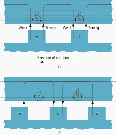
Distortion of flux due to armature reaction

Figure 2 - Distortion of flux due to armature reaction


The phenomenon is most easily explained by considering a simplified ideal generator with full pitch winding operating at unity p.f., zero lag p.f. and zero lead p.f. When operating at unity p.f., the voltage and current in the stator are in phase, the stator current producing a cross magnetising magneto-motive force (m.m.f.) which interacts with that of the rotor, resulting in a distortion of flux across the pole face.

As can be seen from Figure 2 (a) the tendency is to weaken the flux at the leading edge or effectively to distort the field in a manner equivalent to a shift against the direction of rotation.

If the power factor were reduced to zero lagging, the current in the stator would reach its maximum 90° after the voltage and the rotor would therefore be in the position shown in Figure 2 (b). The stator m.m.f. is now acting in direct opposition to the field.

Similarly, for operation at zero leading power factor, the stator m.m.f. would directly assist the rotor m.m.f. This m.m.f. arising from current flowing in the stator is known as ‘armature reaction‘.

Resource: Network Protection and Automation Guide – Areva

Electrical Safety Standards for LV/MV/HV (Part-1)

$
0
0
Electrical Safety Standards for LV/MV/HV (Part-1)

Electrical Safety Standards for LV/MV/HV (on photo Indonesia's state energy giant - High Voltage Switchyard)

Content

  1. Standard: Western Power Company
  • Standard: New Zealand Electrical Code
  • Standard: ETSA Utilities
  • Standard: UK Power Networks – EI 02-0019
  • 1. Standard: Western Power Company

    Water Safely Clearance on Electrical Fires

    VoltageMinimum distances between a nozzle producing a fog stream of fresh water and a live conductor
    Up to 750 V1.5 Meter
    750 V to 15 KV4.0  Meter
    15 KV to 230 KV5.0 Meter

    Go to Content ↑


    Minimum Approach Distance for Authorized Person

    This is the minimum distance that must be maintained by a person, vehicle or mobile plant.

    VoltageDistance (minimum)
    Up to 1 KV0.7 Meter
    1 V to 6.6 KV0.7 Meter
    6.6 KV to 11 KV0.7 Meter
    11 KV to 22 KV0.7 Meter
    22 KV to 33 KV1.0 Meter
    33 KV to 66 KV1.0 Meter
    66 KV to 132 KV1.2 Meter
    132 KV to 220 KV1.8 Meter
    220 KV to 330 KV3.0 Meter

    Go to Content ↑


    Minimum Approach Distance for Ordinary Person

    VoltageDistance  (min)
    Up to 1 KV3.0 Meter
    1 V to 6.6 KV3.0 Meter
    6.6 KV to 11 KV3.0 Meter
    11 KV to 22 KV3.0 Meter
    22 KV to 33 KV3.0 Meter
    33 KV to 66 KV3.0 Meter
    66 KV to 132 KV3.0 Meter
    132 KV to 220 KV4.5 Meter
    220 KV to 330 KV6.0 Meter

    Go to Content ↑


    Minimum Approach Distance for Vehicle and Plant for Ordinary Person

    VoltageDistance  (min)
    Mobile PlantVehicle
    Up to 1 KV3.0 Meter0.6 Meter
    1 V to 6.6 KV3.0 Meter0.9 Meter
    6.6 KV to 11 KV3.0 Meter0.9 Meter
    11 KV to 22 KV3.0 Meter0.9 Meter
    22 KV to 33 KV3.0 Meter0.9 Meter
    33 KV to 66 KV3.0 Meter2.1 Meter
    66 KV to 132 KV3.0 Meter2.1 Meter
    132 KV to 220 KV3.0 Meter2.9 Meter
    220 KV to 330 KV6.0 Meter3.4 Meter

    Go to Content ↑

    2. Standard: New Zealand Electrical Code

    Min. Safe Distance between Buildings and Overhead Line

    VoltagePoleTower
    11 kV to 33 kV2 Meter2 Meter
    33 kV to 66 kV6 Meter6 Meter
    66 kV and Above8 Meter8 Meter

    Go to Content ↑


    Min. Safe Distance for excavation near Overhead Line

    Description of ClearanceFrom Pole (Min)From Tower (min)
    Excavation in land more than 750mm depth8 Meter12 Meter
    Excavation in land up to750mm depth2.2 to 5 Meter6 to12 Meter
    Excavation in land up to 300mm depth2.2 Meter6 Meter
    Construction near 11KV to 33KV Line2.2 Meter6 Meter
    Construction near 33KV to 66KV Line6 Meter9  Meter
    Construction near 66KV and more8 Meter12 Meter
    Wire Fence near 1KV to 66KV Line2.2 Meter2.2 Meter
    Wire Fence near 66KV and more5 Meter5 Meter

    Go to Content ↑


    Min. Safe Distance for Tower Carin near Electrical Tower

    Description of ClearanceDistance (Min)
    Mobile Carin movement4.0 Meter
    Tower Carin movement4.0 Meter
    Carin movement4.0 Meter
    Moving Activity above height of Tower4.0 Meter
    Hedge Cutter  movement4.0 Meter

    Go to Content ↑


    Min. Safe Vertical Distance above Railway Track

    Description of ClearanceDistance (Min)
    Earthed conductors5.5 Meter
    Stay wires5.5 Meter
    Conductors up to 33 kV6.5 Meter
    Conductors above 33 kV to 220 kV7.5 Meter
    Conductors above 220 kV.8 Meter

    Go to Content ↑


    Min. Distance between two Conductors on Same Supports

    High Voltage CircuitHigh Voltage CircuitDistance  between circuits (min)
    Up to 33 KVUp to 1KV1.0 Meter
    Up to 33 KVMore than 1KV1.2 Meter
    33 KV to 110 KVUp to 1KV1.5 Meter
    33 KV to 110 KVMore than 1KV2.0 Meter
    More than 110 KVAll2.5 Meter

    Go to Content ↑


    Min. Distance between two Conductors on Different Supports

    High Voltage CircuitDistance (min)
    Up to 1 KV0.6 Meter
    1 KV to 33 KV1.2 Meter
    33 KV to 66 KV1.8 Meter
    110 KV2.4 Meter
    More than 220 KV2.8 Meter

    Go to Content ↑


    Min. Safety Distance from Electrical Apparatuses

    Description of ClearanceDistance (min)
    Passage In front of Metal-Clad Switchgear (UP to HV)1.0 Meter wide 2.5 Height
    Passage In rear or side of Metal-Clad Switchgear (UP to HV)1.0 Meter wide 2.2 Height
    Passage at any side of Metal-Clad Switch gear containing Bare conductor (UP to HV)0.8 Meter wide 2.2 Height

    Go to Content ↑


    Min. Approach Distance for Non-Competent Person near exposed Live Parts

    VoltageDistance (min)
    Below 110 kV4.0 Meter
    220 kV and above6.0 Meter

    Go to Content ↑


    Min. Approach Distance for Competent Person near exposed Live Parts

    VoltageDistance (min)
    Below 1 kV0.5 Meter
    11 kV1.5 Meter
    22 kV2.0 Meter
    33 kV2.5 Meter
    66 kV3.0 Meter
    110 kV4.0 Meter
    220 kV and above6.0 Meter

    Go to Content ↑

    3. Standard: ETSA Utilities

    Vertical Clearances between Services

    ServiceLV CableHV Cable
    Common Pipe0.100 Meter0.100 Meter
    Gas Pipe0.200 Meter0.200 Meter
    Sewer Pipe0.300 Meter0.300 Meter
    Water Pipe0.600 Meter0.600 Meter

    Go to Content ↑


    Horizontal Clearances between Services

    ServiceLV CableHV Cable
    Common Pipe0.100 Meter0.100 Meter
    Gas Pipe0.200 Meter0.200 Meter
    Sewer Pipe1.0 Meter1.0 Meter
    Water Pipe0.600 Meter0.600 Meter

    Go to Content ↑

    4. Standard: UK Power Networks – EI 02-0019

    Cable Installation Depths

    VoltageAreaDepth (min)
    Low VoltageFootways, grass verges or private property0.450 Meter
    Carriageways (including road crossings)0.600 Meter
    Normal agricultural land (not deep ploughing)1.0 Meter
    Agricultural land subject to deep ploughing1.2 Meter
    11 KV to 20 KVFootways, grass verges or private property0.600 Meter
    Carriageways (including road crossings)0.750 Meter
    Normal agricultural land (not deep ploughing)1.0 Meter
    Agricultural land subject to deep ploughing1.2 Meter
    33 KV to 132 KVFootways, grass verges or private property0.9 Meter
    Carriageways (including road crossings)0.9 Meter
    Normal agricultural land (not deep ploughing)1.0 Meter
    Agricultural land subject to deep ploughing1.2 Meter
    Auxiliary Multi-core & Multi-pair CablesFootways, grass verges or private property0.450 Meter
    Carriageways (including road crossings)0.600 Meter
    Normal agricultural land (not deep ploughing)1.0 Meter
    Agricultural land subject to deep ploughing1.2 Meter
    On Cable Ladder for LV to HVThe Horizontal clearance between cables on cable ladders2X Dia of Cable of Largest Cable or min 150 mm
    The clearance from a supporting wall20 mm
    The vertical clearance between cables is greater150 mm
    If the number of cables > 4, they are to be installed in a horizontal

    Go to Content ↑


    Minimum Approach Distance of Crane or Moving Part from Live Conductor

    VoltageWithout Safety ObservationFor ordinary Person
    Un insulated portionsInsulated portions
    Up to 1KV2 Meter1.0 Meter3.0 Meter
    11 KV2 Meter1.4 Meter3.0 Meter
    22 KV2.4 Meter2 Meter3.0 Meter
    33 KV2.4 Meter2 Meter3.0 Meter
    66 KV2.8 Meter2 Meter3.0 Meter
    132 KV3.0 Meter3.0 Meter3.0 Meter
    220 KV4.8 Meter4.8 Meter6.0 Meter
    330 KV6.0 Meter6.0 Meter6.0 Meter
    500 KV8.0 Meter8.0 Meter8.0 Meter

    Go to Content ↑


    Minimum Fixed Clearances for Electrical Apparatus (Isolation Points)

    VoltageFixed Clearance
    Up to 11Kv0.320 Meter
    11KV to 33KV0.320 Meter
    33KV to 66KV0.630 Meter
    66KV to 132KV1.1 Meter

    Go to Content ↑

    How to Dim LED Lighting in the Home?

    $
    0
    0
    How to Dim LED Lighting in the Home

    How to Dim LED Lighting in the Home? (On photo Dimmer Switch)

    Introduction

    LED lighting in the home is becoming more popular due to the energy and money saving benefits it offers over traditional halogen lighting. One of the most common problems that an electrician faces when installing LED’s is enabling them to dim.


    Resistive Dimming

    Resistive dimming has become a standard way of dimming halogen lighting and it works by reducing the voltage allowed to the bulb with a variable resistor.

    A resistive dimmer switch is easy to install because it is simply wired between the mains (240V) power and the bulb, however whilst the lighting is dimmed the voltage resistance is converted to heat and is not considered energy efficient.

    LED’s use between 12V to 48V so a transformer is required to convert mains power (110V-240V) to the required reduced voltage. Using a resistive dimmer between the main voltage and the transformer will damage the transformer and using a resistive dimmer between the transformer and the LED will cause it to flicker instead of dimming.

    Note: LED’s cannot be dimmed using resistive dimming; it will slowly damage the LED’s.


    Pulse-Width Modulation Dimming

    Pulse-width modulation works by switching the voltage on and off at a variable speed. This causes a flickering effect that is too quick for the human eye to see. By increasing and decreasing the switching speed it increases and decreases the max possible light output and dims the LED.

    PWM dimming is energy efficient because unlike the resistive dimming the more the LED is dimmed the less wattage it uses.

    A problem found with PWM dimming is as the amount of dimming increases so does the amount of time the voltage is turned off. This will eventually fall within the flickering speed in which the human eye can see.

    This flickering can normally be seen when the LED is dimmed to below 10% of its original light output.

    Pulse-Width Modulation Dimming

    Figure 1 - Pulse-Width Modulation Dimming

    TRIAC Dimming

    A TRIAC (Triode for Alternating Current) dimmer works by conducting the current in both directions, alternating at a variable speed. This makes the switching much faster than Pulse-width modulation dimming so it never goes within the flickering speed of the human eye.

    TRIAC Dimming

    Figure 2 - TRIAC Dimming

    Dimming Signals

    Both PWM and TRIAC dimmer modules require a signal to tell the dimmer how much to dim the LED’s. The current standard is 0-10V.


    0-10V Dimming

    0-10V signals work by sending a separate 10v signal to the PWM/TRIAC dimmer module and then using a resistive dimmer to reduce the voltage on the 10V signal. As the voltage drops the dimmer module reduces the brightness on the LED’s in relation to the voltage.

    Example:
    10V = Dim at 100%
    8V = Dim at 80%
    3V =Dim at 30%


    DALI Dimming

    DALI is an open source 2 way protocol designed for controlling lighting in the home. It is a royalty free standard meaning it is possible to mix and match DALI module’s from different manufactures. DALI works by assigning zones and linking all the DALI modules for each zone together.

    The DALI controller can then control multiple zones individually.


    DMX Dimming

    The DMX 512 protocol was originally designed to control nightclub and theatre lighting and has only recently started to be used in the home.

    DMX works by sending a data signal with a value between 0-255 on each channel. There can be a maximum of 512 channels and the signal carries the information for all the channels to each dimmer module receiving the DMX.

    This means that each dimmer module is given a DMX address so it knows which channel to read and adjust the brightness accordingly. Each dimmer module has a DMX In and DMX out socket so the data signal can be daisy chained from one module to next.

    DMX can control colour changing lighting as well as non-lighting devices. E.G. Fog machines, Blinds and even motorised doors.

    Steps to Ensure Effective Substation Grounding (1)

    $
    0
    0
    Steps to ensure effective substation grounding

    Steps to ensure effective substation grounding (photo by peterhousephotography.co.uk)

    Substation Grounding

    An electrical substation is a critical resource in a power system. Safe operation of a substation calls for a properly designed and installed grounding system. A well-designed grounding system will ensure reliable performance of the substation over its entire service life.

    How does good grounding improve substation reliability?

    Good grounding path of sufficiently low impedance ensures fast clearing of faults. A fault remaining in the system for long may cause several problems including those of power system stability. Faster clearing thus improves overall reliability.

    It also ensures safety.

    A ground fault in equipment causes the metallic enclosure potential to rise above the ‘true’ ground potential. An improper grounding results in a higher potential and also results in delayed clearing of the fault (due to insufficient current flow).

    This combination is essentially unsafe because any person coming into contact with the enclosure is exposed to higher potentials for a longer duration.

    Therefore, substation reliability and safety must be as ‘built-in’ as possible by good grounding scheme, which in turn will ensure faster fault clearing and low enclosure potential rise.


    Ensuring Proper Grounding

    The following steps, when put into practice, will ensure a reliable, safe and trouble-free substation grounding system:

    1. Size conductors for anticipated faults
    2. Use the right connections
    3. Ground rod selection
    4. Soil preparation
    5. Attention to step and touch potentials
    6. Grounding using building foundations **
    7. Grounding the substation fence **
    8. Special attention to operating points **
    9. Surge arrestors must be grounded properly **
    10. Grounding of cable trays **
    11. Temporary grounding of normally energized parts **

    ** Will be published in next part of this technical article

    1. Size Conductors For Anticipated Faults

    Conductors must be large enough to handle any anticipated faults without fusing (melting).

    Failure to use proper fault time in design calculations creates a high risk of melted conductors. Two aspects govern the choice of conductor size: the first is the fault current that will flow through the conductor and the second is the time for which it can flow.

    The fault current depends on the impedance of the ground fault loop. The time of current flow is decided by the setting of the protective relays/circuit-breaking devices, which will operate to clear the fault.

    The IEEE 80 suggests using a time of 3.0 s for the design of small substations. This time is also equal to the short-time rating of most switchgear.

    Go to Grounding Steps ↑


    2. Use the Right Connections

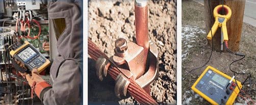
    Grounding Connections, Resistance Test and Bonding Test

    Grounding Connections, Resistance Test and Bonding Test


    It is very evident that the connections between conductors and the main grid and between the grid and ground rods are as important as the conductors themselves in maintaining a permanent low-resistance path to ground.

    The basic issues here are:

    1. The type of bond used for the connection of the conductor in its run, with the ground grid and with the ground rod
    2. The temperature limits, which a joint can withstand.
    The most frequently used grounding connections are mechanical pressure type (which will include bolted, compression and wedge-type construction) and exothermically welded type.

    Pressure-type connections produce a mechanical bond between conductor and connector by means of a tightened bolt-nut or by crimping using hydraulic or mechanical pressure. This connection either holds the conductors in place or squeezes them together, providing surface-to-surface contact with the exposed conductor strands.

    On the other hand, the exothermic process fuses the conductor ends together to form a molecular bond between all strands of the conductor.

    Temperature limits are stated in standards such as IEEE 80 and IEEE 837 for different types of joints based on the joint resistance normally obtainable with each type. Exceeding these temperatures during flow of fault currents may result in damage to the joint and cause the joint resistance to increase, which will result in further overheating.

    The joint will ultimately fail and result in grounding system degradation or total loss of ground reference with disastrous results.

    Go to Grounding Steps ↑


    3. Ground Rod Selection

    Substation grounding rod

    Substation grounding rod


    In MV and HV substations, where the source and load are connected through long overhead lines, it often happens that the ground fault current has no metallic path and has to flow through the groundmass (earth). This means that the ground rods of both source and load side substations have to carry this current to or from the groundmass.

    The ground rod system should be adequate to carry this current and ground resistance of the grounding system assumes importance.

    The length, number and placement of ground rods affect the resistance of the path to earth. Doubling of ground rod length reduces resistance by a value of 45%, under uniform soil conditions. Usually, soil conditions are not uniform and it is vital to obtain accurate data by measuring ground rod resistance with appropriate instruments.

    For maximum efficiency, grounding rods should be placed no closer together than the length of the rod. Normally, this is 10 ft (3 m). Each rod forms an electromagnetic shell around it, and when the rods are too close, the ground currents of the shells interfere with each other.

    It should be noted that as the number of rods is increased, the reduction of ground resistance is not in inverse proportion. Twenty rods do not result in 1/20th of the resistance of a single rod but only reduce it by a factor of 1/10th.

    For economic reasons, there is a limit to the maximum distance between rods.

    Normally, this limit is taken as 6 m. At more than 6 m, the cost of additional conductor needed to connect the rods makes the design economically attractive.

    In certain cases, the substation layout may not have the required space and acquiring the needed space may involve substantial expense. Four interconnected rods on 30 m centers will reduce resistivity 94% over one rod but require at least 120 m of conductor.

    On the other hand, four rods placed 6 m apart will reduce resistivity 81% over one rod and use only 24 m of conductor.

    Go to Grounding Steps ↑


    4. Soil Preparation

    Soil resistivity is an important consideration in substation grounding system design. The lower the resistivity, the easier it is to get a good ground resistance.

    Areas of high soil resistivity and those with ground frost (which inturn causes the soil resistivityto increase by orders of magnitude) need special consideration. The highest ground resistivity during the annual weather cycle should form the basis of the design since the same soil will have much higher resistivity during dry weather when percentage of moisture in the ground becomes very low.

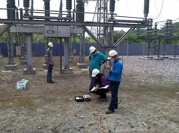
    Grounding Tests: · Earth Potential and Grounding Mesh Effectiveness.

    Grounding Tests: · Earth Potential and Grounding Mesh Effectiveness.


    One approach to take care of this problem is to use deep driven ground rods so that they are in contact with the soil zone deep enough to remain unaffected by surface climate.

    The other approach is to treat the soil around the ground rod with chemical substances that have the capacity to absorb atmospheric/soil moisture.

    Use of chemical rods is one such solution.

    Go to Grounding Steps ↑


    5. Attention to Step and Touch Potentials

    Limiting step and touch potential to safe values in a substation is vital to personnel safety.

    Step potential is the voltage difference between a person’s feet and is caused by the voltage gradient in the soil at the point where a fault enters the earth. The potential gradient is steepest near the fault location and thereafter reduces gradually. Just 75 cm away from the entry point, voltage usually will have been reduced by 50%.

    Thus at a point of 75 cm from the fault (which is less than the distance of a normal step), a fatal potential of a few kilovolts can exist.

    Touch potential represents the same basic hazard, except the potential exists between the person’s hand and his or her feet. This happens when a person standing on the ground touches a structure of the substation, which is conducting the fault current into ground (for example, when an insulator fixed on a gantry flashes over, the gantry dissipates the current to earth).

    Since the likely current path within the human body runs through the arm and heart region instead of through the lower extremities, the danger of injury or death is far greater in this case. For this reason, the safe limit of touch potential is usually much lower than that of step potential.

    In both situations, the potential can essentially be greatly reduced by an equipotential wire mesh safety mat installed just below ground level.

    This mesh will have to be installed in the immediate vicinity of any switches or equipment a worker might touch, and connected to the main ground grid. Such an equipotential mesh will equalize the voltage along the worker’s path and between the equipment and his or her feet. With the voltage difference (potential) thus essentially eliminated, the safety of personnel is virtually guaranteed.

    An equipotential wire mesh safety mat is usually fabricated from #6 or #8 AWG copper or copper-clad wire to form a 0.5 ×0.5 m or 0.5 ×1 m mesh. Many other mesh sizes are available.

    To ensure continuity across the mesh, all wire crossings are brazed with a 35% silver alloy. Interconnections between sections of mesh and between the mesh and the main grounding grid should be made so as to provide a permanent low-resistance high-integrity connection.

    Go to Grounding Steps ↑

    To bi continued in part 2…

    Resource: Practical Grounding, Bonding, Shielding and Surge Protection – G. Vijayaraghavan; Mark Brown; Malcolm Barnes (Get this book at Amazon)

    Steps to Ensure Effective Substation Grounding (2)

    $
    0
    0
    Steps to Ensure Effective Substation Grounding

    Steps to Ensure Effective Substation Grounding (photo by Peak Power Engineering, Inc.)


    Continued from previous article: Steps to Ensure Effective Substation Grounding (1)

    Ensuring Proper Grounding

    In previous technical article (part 1) was explained first five steps that will ensure a reliable, safe and trouble-free substation grounding system. Here we will explain the last six steps:

    1. Size conductors for anticipated faults (previous part 1)
    2. Use the right connections (previous part 1)
    3. Ground rod selection (previous part 1)
    4. Soil preparation (previous part 1)
    5. Attention to step and touch potentials (previous part 1)
    6. Grounding using building foundations
    7. Grounding the substation fence
    8. Special attention to operating points
    9. Surge arrestors must be grounded properly
    10. Grounding of cable trays
    11. Temporary grounding of normally energized parts

    6. Grounding Using Building Foundations

    The concrete operation to Building control foundation

    The concrete operation to Building control foundation

    Concrete foundations below ground level provide an excellent means of obtaining a low-resistance ground electrode system. Since concrete has a resistivity of about 30 Ωm at 20 °C, a rod embedded within a concrete encasement gives a very low electrode resistance compared to most rods buried in the ground directly.

    Since buildings are usually constructed using steel-reinforced concrete, it is possible to use the reinforcement rod as the conductor of the electrode by ensuring that an electrical connection can be established with the main rebar of each foundation.

    The size of the rebar as well as the bonding between the bars of different concrete members must be done so as to ensure that ground fault currents can be handled without excessive heating.

    Such heating may cause weakening and eventual failure of the concrete member itself. Alternatively, copper rods embedded within concrete can also be used.

    The use of ‘Ufer’ grounds (named after the person who was instrumental in the development of this type of grounding practice) has significantly increased in recent years. Ufer grounds utilize the concrete foundation of a structure plus building steel as a grounding electrode.

    Even if the anchor bolts are not directly connected to the reinforcing bars (rebar), their close proximity and the conductive nature of concrete will provide an electrical path.

    There are a couple of issues to be considered while planning for grounding using the foundations as electrodes. A high fault current (lightning surge or heavy ground fault) can cause moisture in the concrete to evaporate suddenly to steam.

    This steam, whose volume is about 1800 times of its original volume when existing as liquid, produces forces that may crack or otherwise damage the concrete. The other factor has to do with ground leakage currents. The presence of even a small amount of DC current will cause corrosion of the rebar. Because corroded steel swells to about twice its original volume, it can cause extremely large forces within the concrete.

    Although AC leakage will not cause corrosion, the earth will rectify a small percentage of the AC to DC. In situations where the anchor bolts are not bonded to the rebar, concrete can disintegrate in the current path.

    Damage to concrete can be minimized either by limiting the duration of fault current flow (by suitable sensitive and fast acting protective devices) or by providing a metallic path from the rebar through the concrete to an external electrode.

    That external electrode must be sized and connected to protect the concrete’s integrity. Proper design of Ufer grounds provides for connections between all steel members in the foundation and one or more metallic paths to an external ground rod or main ground grid.

    Excellent joining products are available in the market, which are especially designed for joining rebars throughout the construction. By proper joining of the rebars, exceptionally good performance can be achieved.

    An extremely low resistance path to earth for lightning and earth fault currents is ensured as the mass of the building keeps the foundation in good contact with the soil.

    Go to Grounding Steps ↑


    7. Grounding the Substation Fence

     The second most common substation hazard is lack of grounding

    The second most common substation hazard is lack of grounding (photo from IAEI Magazine)


    Metallic fences of substations should be considered just as other substation structures.

    The reason for this is that the overhead HV lines entering or leaving a substation may snap and fall on the fence. Unless the fence is integrated with the rest of the substation grounding system, a dangerous situation may develop. Persons or livestock in contact with the fence may receive dangerous electric shocks.

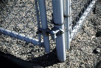
    Utilities vary in their fence-grounding specifications, with most specifying that each gate post and corner post, plus every second or third line post, be grounded. All gates should be bonded to the gate posts using flexible jumpers. All gate posts should be interconnected. In the gate swing area, an equipotential wire mesh safety mat can further reduce hazards from step and touch potentials when opening or closing the gate.

    It is recommended that the fence ground should be tied into the main ground grid, as it will reduce both grid resistance and grid voltage rise. Internal and perimeter gradients must be kept within safe limits because the fence is also atfull potential rise.

    This can be accomplished by extending the mesh with a buried perimeter conductor that is about 1 m outside the fence and bonding the fence and the conductor together at close intervals (so that a person or grazing animal touching the fence will stand on the equipotential surface so created).

    Go to Grounding Steps ↑


    8. Special Attention to Operating Points

    To protect the operator in case of a fault, it should be ensured that he is not subjected to high touch or step potentials when a fault happens in the equipment he is operating.

    This calls for use of a safety mesh close to these operating points on which the operator will stand and operate the equipment.

    There are four types of safety mats.

    1. A steel grate or plate on supporting insulators. This works only if the operator can be kept completely isolated on the grate. Therefore, insulators must be kept clean.

    Any vegetation in the vicinity should be cut or eliminated completely (this approach is similar to the insulating rubber mats placed in front of most indoor electrical equipment). Safety is ensured by increasing the resistance of current path, so that the current flowing through the operator’s body into the ground does not exceed safe values.

    2. A steel grate on the surface, permanently attached to the grounded structure. This arrangement has the operator standing directly on the grate.

    3. Bare conductor buried (in a coil or zig-zag pattern) under the handle area and bonded to the grounded structure.

    4. Prefabricated equipotential wire mesh safety mat buried under the handle area and bonded to the grounded structure. This is likely to be the least expensive choice.

    In all but the first arrangement, both the switch operating handle and the personnel safety grate (or mat) should be exothermically weldedto structural steel, thus ensuring nearly zero voltage drop.

    Go to Grounding Steps ↑


    9. Surge Arrestors Must be Grounded Properly!

    When there is a surge in the electrical system (by indirect lightning strikes or due to switching) surge arrestors placed near all critical equipment divert surge energy to ground and protect the equipment from being subjected to the surges.

    Usually, surges involve a very fast rise time during which the current changes from zero to extremely high values of several kiloamperes. It is therefore necessary that the conducting path from the grounding terminal of the surge arrestor to the earth must have minimum impedance.

    Even a small amount of self-inductance offered by a grounding conductor will mean very high impedance because of the steep wavefront of the surge and very high voltages from appearing in the grounding system (albeit briefly). To dissipate the surge current with minimum voltage drop, each surge arrestor ground lead should have a short direct path to earth and should be free of sharp bends (bends act like a coil and increase the inductance).

    Often surge arrestors are mounted directly on the tank of transformers, close to the HV terminal bushings. In these cases, the transformer tanks and related structures act as the grounding path.

    It must be ensured that multiple and secure paths to ground are available (this includes making effective connections).

    Whenever there is any question about the adequacy of these paths, it is recommended to use a separate copper conductor between the arrestor and the ground terminal (or main grounding grid). Since steel structures (due to their multiple members) have lower impedance than a single copper conductor, the grounding conductors should preferably be interconnected to the structure near the arrestor.

    Go to Grounding Steps ↑


    10. Grounding of Cable Trays

    Overhead cable trays and ladder racks grounded

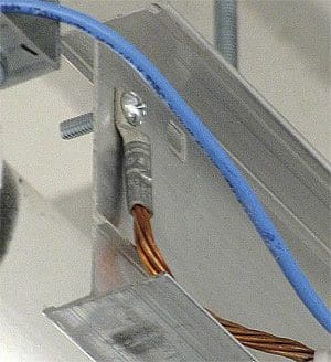
    Overhead cable trays and ladder racks are jumpered and grounded with AWG #2 bare copper. These conductors, along with the cable bus that collects ground leads from individual cabinets, are connected to the nearest wall-mounted collector bar.


    The NEC vide Art. 318 specifies the requirements for cable trays and their use in reducing the induced voltages during a ground fault. All metallic tray sections must be bonded together with proper conducting interconnections. The mechanical splice plates by themselves may not provide an adequate and a reliable ground path for fault currents.

    Therefore, the bonding jumpers (either the welded type used on steel trays or the lug type) must be placed across each spliced tray joint.

    If a metallic tray comes with a continuous grounding conductor, the conductor can be bonded inside or outside the tray.

    When cable tray covers are used, they should be bonded to the tray with a flexible conductor. The trays should also be bonded to the building steel (usually at every other column).

    Go to Grounding Steps ↑


    11. Temporary Grounding of Normally Energized Parts

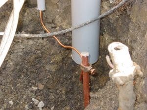
    Temporary grounding of normally energized parts

    Temporary grounding of normally energized parts with ground rod and earth wire clamp


    When personnel work on high-voltage electric structures or equipment, any conductive bodies should be grounded as a measure of safety.

    This is done so that in the event of the circuit becoming live due to inadvertent switching, the safety of personnel (in contact with the parts, which would become live) is ensured.

    The usual grounding method is to attach a flexible insulated copper cable with a ground clamp or lug on each end. These flexible jumpers require periodic inspection and maintenance. For cable connections to clamps, welded terminations (either a welded plain stud or a threaded silicon bronze stud welded to the conductor end) will provide a secure, permanent connection.

    The clamp or lug is solidly connected to ground, then the other clamp is attached to the cable being grounded.

    Go to Grounding Steps ↑

    Resource: Practical Grounding, Bonding, Shielding and Surge Protection – G. Vijayaraghavan; Mark Brown; Malcolm Barnes
    (Get this book at Amazon)

    Electrical Safety Standards for LV/MV/HV (Part-2)

    $
    0
    0
    Electrical Safety Standards for LV/MV/HV part 2

    Electrical Safety Standards for LV/MV/HV part 2 (on photo Downtown LA distribution power lines; photo by Hal Bergman Photography @Flickr)


    Continued from part 1Electrical Safety Standards for LV/MV/HV (Part-1)

    Content

    Standard: Northern Ireland Electricity (NIE), 6/025 ENA

    1. Clearances of Electrical Line to Ground and Roads

    2. Clearances of Electrical Line to Other Objects
    3. Clearances of Electrical Line to Trees and Hedges
    4. Clearances of Electrical Line to Street Lighting
    5. Clearances of Electrical Line to Waterways
    6. Clearances to Railways
    7. Clearances of Electrical Line to Fuel Tanks
    8. Clearances of Electrical Lines to other Electrical Lines
    9. Vertical Passing Clearance (sites where vehicles will pass below the lines)
    10. Horizontal Clearance (sites where there will be no work or passage of plant under lines)
    11. Distance between Conductors of Same/Different Circuit (On Same Support)
    12. Vertical Distance between Conductors of different Circuit (On Different Support)
    13. Distance between Conductors (Taken down from Pole to other Support, on Transformer)
    14. Horizontal Distance of Telecommunication Line & Overhead Line
    15. Passage Way for Metal-Clad Switchgear
    16. Safe approach distance for Person from Exposed Live Parts

    Standard: Northern Ireland Electricity (NIE), 6/025 ENA

    Clearances of Electrical Line to Ground and Roads

    Description of Clearance0.4 KV11 KV33KV110KV220 KV400KV
    Line conductor to any point not over road5.2 Meter6.1 Meter6.4 Meter6.4 Meter7.0 Meter7.0 Meter
    Line conductor to road surface5.8 Meter6.1 Meter6.4 Meter6.4 Meter7.4 Meter8.1 Meter
    Line conductor to road surface of high load routes6.9 Meter6.9 Meter6.9 Meter7.2 Meter8.5 Meter9.2 Meter
    Bare live metalwork ( transformer terminals, jumper connections, etc)4.6 Meter4.6 Meter4.6 Meter---

    Go to Content ↑


    Clearances of Electrical Line to Other Objects

    Description of Clearance<11 KV33 KV110KV220KV400 KV
    Line conductor or bare live metalwork to any object that is normally accessible (including permanently mounted ladders and access platforms) or to any surface of a building3.0 Meter3.0 Meter3.4 Meter4.6 Meter5.3 Meter
    Line conductor or bare live metalwork to any object to which access is not required AND on which a person cannot stand or lean a ladder0.8 Meter0.8 Meter1.2 Meter2.4 Meter3.1 Meter
    Line conductors to irrigates, slurry guns and high-pressure hoses30 Meter30 Meter30 Meter30 Meter30 Meter
    Line conductors to playing fields8.5 Meter8.5 Meter8.5 Meter8.5 Meter8.5 Meter
    Line conductors to Caravan Sites9.0 Meter9.0 Meter9.0 Meter9.0 Meter9.0 Meter
    Horizontal clearances to wells15.0 Meter15.0 Meter15.0 Meter15.0 Meter15.0 Meter

    Go to Content ↑


    Clearances of Electrical Line to Trees and Hedges

    Description of Clearance<11 KV33 KV110KV220KV400 KV
    Line conductor or bare live metalwork to trees or hedges unable to support a ladder or being climbed.0.8 Meter0.8 Meter1.2 Meter2.4 Meter3.1 Meter
    Line conductor or bare live metalwork to trees or hedges capable of supporting a ladder or being climbed.3.0 Meter3.0 Meter3.4 Meter4.6 Meter5.3 Meter
    Line conductor or bare live metalwork to trees falling towards the overhead line with the line conductors hanging vertically.0.8 Meter0.8 Meter1.2 Meter2.4 Meter3.1 Meter
    Line conductors to trees in Orchards3.0 Meter3.0 Meter3.4 Meter4.6 Meter5.3 Meter

    Go to Content ↑


    Clearances of Electrical Line to Street Lighting

    Description of Clearance0.4 KV11 KV33KV110KV220 KV400KV
    Line conductor to Lantern on same pole1.0 Meter-----
    Bare line conductor to lantern or column below.1.5 Meter-----
    Insulated line conductor to column0.3 Meter-----
    Insulated line conductor to lantern1.0 Meter-----
    Column to nearest LV pole1.5 Meter-----
    Line conductor to street lighting column with
    (1) Column in normal upright position.-1.7 Meter1.7 Meter2.3 Meter3.3 Meter4.0 Meter
    (2) Column falling towards line with line conductor hanging vertically only-1.7 Meter1.7 Meter2.3 Meter3.3 Meter4.0 Meter
    (3) Column falling towards line-0.4 Meter0.4 Meter0.8 Meter1.4 Meter1.9 Meter

    Go to Content ↑


    Clearances of Electrical Line to Waterways

    Description of Clearance0.4 KV11 KV33KV110KV220 KV400KV
    Navigable Waters: Lower bank to conductor or earth wire10.5 Meter10.5 Meter10.5 Meter10.5 Meter10.5 Meter10.5 Meter
    Minor Watercourses : Lower bank to conductor or earth wire7.6 Meter7.6 Meter7.6 Meter7.6 Meter7.6 Meter7.6 Meter

    Go to Content ↑


    Clearances to Railways

    Description of Clearance0.4 KV11 KV33KV110KV220 KV400KV
    Line conductor to ground level6.1 Meter6.1 Meter6.1 Meter6.7 Meter7.0 Meter7.6 Meter
    Line conductor to ground level on or across vehicle parks7.6 Meter8.5 Meter8.5 Meter9.1 Meter9.4 Meter10.1 Meter
    Line conductor to ground level at roads and yards, where road mobile cranes are likely to be employed10.7 Meter10.7 Meter10.7 Meter11.2 Meter11.5 Meter12.2 Meter
    Line conductor to Rail level7.3 Meter7.3 Meter7.3 Meter8.0 Meter8.2 Meter8.8 Meter
    Line conductor to the level of buildings, gantries or other structures (including those carrying traction wires) on which a man may be3.0 Meter3.0 Meter3.0 Meter3.7 Meter4.6 Meter6.1 Meter
    Line conductor to poles and other projections.2.4 Meter2.7 Meter2.7 Meter3.0 Meter3.7 Meter5.5 Meter
    Line conductor to any other wire other than traction wires.1.8 Meter1.8 Meter1.8 Meter2.4 Meter3.0 Meter3.7 Meter

    Go to Content ↑


    Clearances of Electrical Line to Fuel Tanks>

    Description of Clearance0.4 KV11 KV33KV110KV220 KV400KV
    Horizontal clearance from line conductors to petrol tanks and vents15 Meter15 Meter15 Meter15 Meter15 Meter15 Meter
    Horizontal clearance from line conductors to liquid gas tanks
    (1) 459 to 2273 litre capacity3.0 Meter3.0 Meter3.0 Meter3.4 Meter4.6 Meter5.3 Meter
    (2) 2274 to 9092 litre capacity7.6 Meter7.6 Meter7.6 Meter7.6 Meter7.6 Meter7.6 Meter
    (3) More than 9093 litre.15 Meter15 Meter15 Meter15 Meter15 Meter15 Meter
    Vertical clearance from line conductors to fuel oil tanks Please refer Clearances to Objects

    Go to Content ↑


    Clearances of Electrical Lines to other Electrical Lines

    Description of Clearance0.4 KV11 KV33KV110KV220 KV400KV
    Lowest line conductor or earth wire of upper line to highest line conductor of lower line.1.0 Meter1.8 Meter2.0 Meter2.5 Meter3.7 Meter4.4 Meter
    Lowest line conductor or earth wire of upper line to earth wire of lower line where erected.0.7 Meter1.4 Meter1.6 Meter2.5 Meter3.7 Meter4.4 Meter
    Lowest line conductor or earth wire of upper line to any point on a support of the lower line on which a person may stand.2.7 Meter2.8 Meter3.0 Meter3.4 Meter4.6 Meter5.3 Meter
    Support of upper line and any conductor of lower line.7.5 Meter7.5 Meter7.5 Meter15 Meter15 Meter15 Meter

    Go to Content ↑


    Vertical Passing Clearance (sites where vehicles will pass below the lines)

    Description of Clearance<33 KV110KV220KV400 KV
    Passing clearance: fixed height loads0.8 Meter1.4 Meter2.4 Meter3.1 Meter
    Passing Clearance: variable height loads.2.3 Meter3.2 Meter4.1 Meter5.0 Meter

    Go to Content ↑


    Horizontal Clearance (sites where there will be no work or passage of plant under lines)

    Description of Clearance<33 KV110KV220KV400 KV
    Minimum horizontal distances to safety barriers6.0 Meter9.0 Meter12.0 Meter14.0 Meter

    Go to Content ↑


    Distance between Conductors of Same/Different Circuit (On Same Support)

    Higher Voltage of either CircuitLower Voltage of either CircuitDistance between Circuits
    < 33 KV< 1 KV1.0 Meter
    < 33 KV> 1 KV1.2 Meter
    33 KV to 110 KV< 1 KV1.5 Meter
    33 KV to 110 KV> 1 KV2.0 Meter
    Above 110 KVAll2.5 Meter

    Go to Content ↑


    Vertical Distance between Conductors of different Circuit (On Different Support)

    Higher Voltage of either CircuitDistance between Circuits
    < 1 KV0.6 Meter
    1 KV to 33 KV1.2 Meter
    33 KV to 66 KV1.8 Meter
    110 KV2.4 Meter
    220 KV2.8 Meter

    Go to Content ↑


    Distance between Conductors (Taken down from Pole to other Support, on Transformer)

    VoltageDistance between Circuits
    11 KV & LV Line0.60 Meter
    22 KV & LV Line0.75 Meter
    33 KV & LV Line0.90 Meter

    Go to Content ↑


    Horizontal Distance of Telecommunication Line & Overhead Line

    Description of ClearanceDistance
    Telecommunication Line(Not insulated) to HV LineMin 1.6 Meter
    Telecommunication Line (Bare) to LV (Bare) LineMin 1.2 Meter
    Telecommunication Line (Covered) to LV (Bare) LineMin 0.6 Meter
    Telecommunication Line (Bare) to Stay (Bare) WireMin 0.3 Meter

    Go to Content ↑


    Passage Way for Metal-Clad Switchgear

    Description of ClearanceDistance
    Clean &unobstructed Passages at the front of any Low/High Voltage Switchgear.1.0 Meter wide & 2.5 Meter high
    Clean &unobstructed Passages at side or under any earthed enclosure containing Bare Conductor0.8 Meter wide & 2.2 Meter high

    Go to Content ↑


    Safe approach distance for Person from Exposed Live Parts

    Circuit VoltageDistance
    < 1 KV0.5 Meter
    11 KV1.5 Meter
    22 KV2.0 Meter
    33 KV2.5 Meter
    66 KV3.0 Meter
    110 KV4.0 Meter
    >220 KV6.0 Meter

    Go to Content ↑


    Principles and Characteristics of Distance Protection

    $
    0
    0
    Principles and Characteristics of Distance Protection

    Principles and Characteristics of Distance Protection (on photo distance protection relay type SIPROTEC 4 7SA522 for transmission lines)

    Introduction to Distance Protection

    Distance relays are one of the most important protection elements in a transmission line.

    These  relays may sometimes be set based in percentages of the line impedances, for example a  typical setting for zone 1 is 80% of the impedance of the line in order to not reach the remote  end, the zone 2 can be set at 120% of the impedance of the line in order to dependably  overreach the line, Zone 3 sometimes are disabled or set to cover an adjacent line.

    Distance relays characteristics may be Mho, Quadrilateral, Offset Mho, etc. In the case of the  quadrilateral characteristic or long reaching mho characteristics, additional care may be  required to remain secure during heavy load.

    In the case of parallel lines, the mutual coupling of these lines can cause distance relays to  under reach and over reach. For this reason the relay setting must consider this effect, some  relays have algorithms to compensate, but it is necessary to use the current of the parallel line  which adds complexity to the installation.

    In some countries there criteria that a distance protection can not reach fault in other voltage  levels, because fault clearing times in sub transmission levels may be slower than fault clearing  times at the transmission level.

    The problem of combining fast fault clearance with selective tripping of plant is a key aim for the protection of power systems.

    To meet these requirements, high-speed protection systems for transmission and primary distribution circuits that are suitable for use with the automatic reclosure of circuit breakers are under continuous development and are very widely applied.

    Distance protection, in its basic form, is a non-unit system of protection offering considerable economic and technical advantages.

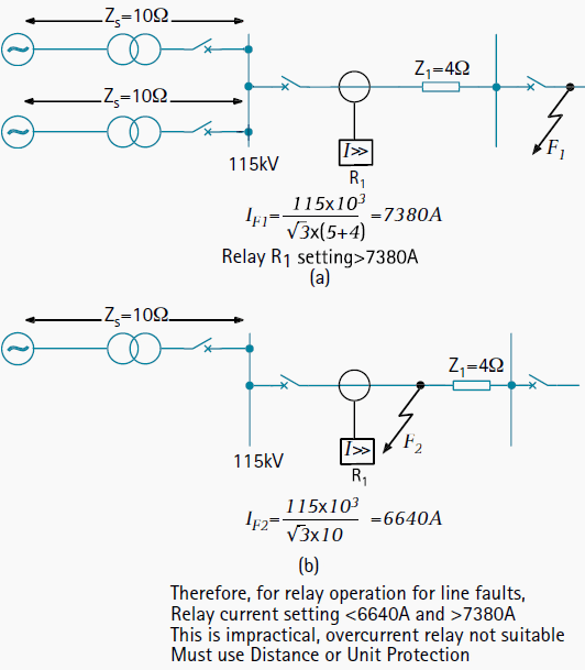
    Unlike phase and neutral overcurrent protection, the key advantage of distance protection is that its fault coverage of the protected circuit is virtually independent of source impedance variations.

    Advantages of distance over overcurrent protection

    Figure 1 - Advantages of distance over overcurrent protection

    Distance protection is comparatively simple to apply and it can be fast in operation for faults located along most of a protected circuit. It can also provide both primary and remote back-up functions in a single scheme. It can easily be adapted to create a unit protection scheme when applied with a signalling channel.

    In this form it is eminently suitable for application with high-speed auto- reclosing, for the protection of critical transmission lines.


    Principles of Distance Relays

    Since the impedance of a transmission line is proportional to its length, for distance measurement it is appropriate to use a relay capable of measuring the impedance of a line up to a predetermined point (the reach point).

    Such a relay is described as a distance relay and is designed to operate only for faults occurring between the relay location and the selected reach point, thus giving discrimination for faults that may occur in different line sections.

    The basic principle of distance protection involves the division of the voltage at the relaying point by the measured current. The apparent impedance so calculated is compared with the reach point impedance. If the measured impedance is less than the reach point impedance, it is assumed that a fault exists on the line between the relay and the reach point.

    The reach point of a relay is the point along the line impedance locus that is intersected by the boundary characteristic of the relay.

    Since this is dependent on the ratio of voltage and current and the phase angle between them, it may be plotted on an R/X diagram. The loci of power system impedances as seen by the relay during faults, power swings and load variations may be plotted on the same diagram and in this manner the performance of the relay in the presence of system faults and disturbances may be studied.


    Relay performance

    Distance relay performance is defined in terms of reach accuracy and operating time. Reach accuracy is a comparison of the actual ohmic reach of the relay under practical conditions with the relay setting value in ohms.

    Reach accuracy particularly depends on the level of voltage presented to the relay under fault conditions.

    The impedance measuring techniques employed in particular relay designs also have an impact. Operating times can vary with fault current, with fault position relative to the relay setting, and with the point on the voltage wave at which the fault occurs.

    Depending on the measuring techniques employed in a particular relay design, measuring signal transient errors, such as those produced by Capacitor Voltage Transformers or saturating CT’s, can also adversely delay relay operation for faults close to the reach point. It is usual for electromechanical and static distance relays to claim both maximum and minimum operating times.

    However, for modern digital or numerical distance relays, the variation between these is small over a wide range of system operating conditions and fault positions.


    Distance Relay Characteristics

    Some numerical relays measure the absolute fault impedance and then determine whether operation is required according to impedance boundaries defined on the R/X diagram.

    Traditional distance relays and numerical relays that emulate the impedance elements of traditional relays do not measure absolute impedance. They compare the measured fault voltage with a replica voltage derived from the fault current and the zone impedance setting to determine whether the fault is within zone or out-of-zone. Distance relay impedance comparators or algorithms which emulate traditional comparators are classified according to their polar characteristics, the number of signal inputs they have, and the method by which signal comparisons are made.

    The common types compare either the relative amplitude or phase of two input quantities to obtain operating characteristics that are either straight lines or circles when plotted on an R/X diagram. At each stage of distance relay design evolution, the development of impedance operating characteristic shapes and sophistication has been governed by the technology available and the acceptable cost.

    Since many traditional relays are still in service and since some numerical relays emulate the techniques of the traditional relays, a brief review of impedance comparators is justified.


    Example of Modern Distance Protection Relay

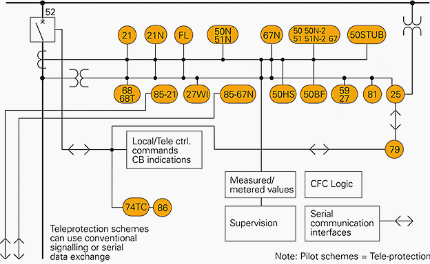
    SIPROTEC 7SA522 protection relay - Single line diagram

    SIPROTEC 7SA522 protection relay - Single line diagram (provides full-scheme distance protection and incorporates all functions usually required for the protection of a power line)


    This particulary relay has following ANSI protection functions:

    ANSIDescriptionANSIDescription
    21/21NDistance protection50HSSwitch-onto-fault protection
    FLFault locator50BFBreaker failure protection
    50N/51N; 67NDirectional ground-fault protection59/27Overvoltage/undervoltage protection
    50/51/67Backup overcurrent protection81O/UOver/underfrequency protection
    50 STUBSTUB-bus overcurrent stage25Synchro-check
    68/68TPower swing detection/tripping79Auto-reclosure
    85/21Teleprotection for distance protection74TCTrip circuit supervision
    27WIWeak-infeed protection86Lockout (CLOSE command – interlocking)
    85/67NTeleprotection for ground-fault protection

    Distance Relays (VIDEO)

    Cant see this video? Click here to watch it on Youtube.

    Resource: Network protection and automation guide – Areva; SIPROTEC47SA522 – Distance Protection Relay for Transmission Lines; An Example Distance Protection Application with Complicating Factors by Yofre Jacome and Charles F Henville

    Electrical Safety Standards for LV/MV/HV (Part-3)

    $
    0
    0
    Electrical Safety Standards for LV/MV/HV part 3

    Electrical Safety Standards for LV/MV/HV part 3 (On photo transmission tower in India)


    Continued from part 2Electrical Safety Standards for LV/MV/HV (Part-2)

    Content

    Standard: Northern Ireland Electricity (NIE), 6/025 ENA

    Code: Indian Electricity Rules / Central Electricity Authority

    1. Right of Way Clearance (As per GETCO Standard)
    2. Minimum clearances between Electrical Lines crossing each other
    3. Permissible Min ground Clearance of Electrical Line
    4. Clearance for Telephone line Crossings Power Line
    5. Vertical Clearance between Electrical Line and railway tracks
    6. Clearance from Buildings to low, medium & high voltage lines
    7. Clearance above ground at the lowest conductor
    8. Vertical Clearance at Middle of Span
    9. Safety Clearance from Live Part in Outdoor Substation
    10. Lying of Telecommunication Cables with Power Cables (>33 kV)
    11. Safe approach limits for people

    Code: Indian Electricity Rules / Central Electricity Authority

    Right of Way Clearance (As per GETCO Standard)

    KVMin ROW
    66 KV18 Meter
    132 KV27 Meter
    220 KV35 Meter
    400KV52 Meter (Single Circuit)
    400 KV48 Meter (Double Circuit)

    Go to Content ↑


    Minimum clearances between Electrical Lines crossing each other

    Voltage66 KV132 KV220 KV400 KV
    66 KV2.4 Meter3 Meter4.5 Meter5.4 Meter
    132 KV3 Meter3 Meter4.5 Meter5.4 Meter
    220 KV4.5 Meter4.5 Meter4.5 Meter5.4 Meter
    400 KV4.5 Meter5.4 Meter5.4 Meter5.4 Meter

    Go to Content ↑


    Permissible Min ground Clearance of Electrical Line

    KVGround ClearanceOver National Highway
    66 KV6.1 Meter8.0 Meter
    132 KV6.1 Meter8.6 Meter
    220 KV7.0 Meter9.8 Meter
    400KV8.8 Meter10.8 Meter

    Go to Content ↑


    Clearance for Telephone line Crossings Power Line

    KVClearance (Min)
    66 KV2.4 Meter
    132 KV2.7 Meter
    220 KV3.0 Meter

    Go to Content ↑


    Vertical Clearance between Electrical Line and railway tracks

    KVClearance (Min)
    66 KV14 Meter
    132 KV14.6 Meter
    220 KV15.4 Meter
    400 KV17.9 Meter

    Go to Content ↑


    Clearance from Buildings to low, medium and high voltage lines

    VoltageDescriptionDistance
    Low & Medium VoltageFlat roof, open balcony, verandah roof ,When the line passes above the building a vertical clearance from the highest point2.5 Meter
    Low & Medium VoltageLine passes adjacent to the building a horizontal clearance from the nearest point1.2 Meter
    Low & Medium VoltageLine passes above the building a vertical clearance2.5 Meter
    Low & Medium VoltageLine passes adjacent the building a Horizontal clearance1.2 Meter
    11 KV to 33 KVLine passes above or adjacent   to any building or part of a building3.7  Meter
    Above 33 KVLine passes above or adjacent   to any building or part of a building3.7+(0.3 for every additional 33 KV )
    Up to 11 KVThe horizontal clearance between the nearer conductor and any part of such building1.2 Meter
    11 KV to 33 KVThe horizontal clearance between the nearer conductor and any part of such building2.0 Meter
    Above 33 KVThe horizontal clearance between the nearer conductor and any part ofsuch building2.0 + (0.3 for every additional 33 KV )

    Go to Content ↑


    Clearance above ground at the lowest conductor

    VoltageDescriptionDistance
    Low & Medium VoltageAcross a street5.8 Meter
    High VoltageAcross a street6.1 Meter
    Low & Medium VoltageAlong a street5.5 Meter
    High VoltageAlong a street5.8 Meter
    Low & Medium VoltageElsewhere than along or across any street4.0 Meter
    High VoltageElsewhere than along or across any street5.2 Meter
    33 KV & EHVClearance above ground(Add 0.3 Meter for every 33 KV Volts in 5.2 Meter)Min 6.1 Meter

    Go to Content ↑


    Vertical Clearance at Middle of Span

    SpanVertical Clearance (At Middle of Span)
    200 Meter4.0 Meter
    300 Meter5.5 Meter
    400 Meter7.0 Meter
    500 Meter8.5 Meter

    Go to Content ↑


    Safety Clearance from Live Part in Outdoor Substation

    KVSafety Working Clearance
    12 KV2.6 Meter
    36 KV2.8 Meter
    72.5 KV3.1 Meter
    145 KV3.7 Meter
    220 KV4.3 Meter
    400KV6.4 Meter
    800 KV10.3 Meter

    Go to Content ↑


    Lying of Telecommunication Cables with Power Cables (>33 kV)

    CableMin. Distance
    Power cable of voltage exceeding 33 kV shall be laidMin 1.2 Meter depth
    Underground telecommunication cable shall be with underground power cable of voltage exceeding 33 kV.Min 0.6 Meter Separate from Power Cable

    Go to Content ↑


    Safe approach limits for people

    Voltage214V to 415 KV11KV33KV66KV132KV275KV
    Person using manually operated tool1.3 Meter2.0 Meter3.0 Meter4.0 Meter5.0 Meter6.0 Meter
    Person using power operated tool3.0 Meter3.0 Meter3.0 Meter4.0 Meter5.0 Meter6.0 Meter

    Go to Content ↑

    What’s common for Beer Mug and Power Factor?

    $
    0
    0
    What's common for Beer Mug and Power Factor?

    What's common for Beer Mug and Power Factor?


    Understanding power factor is not that hard. We have some very common example from the real life you will understand for sure, but first let’s start with some introduction of power factor.

    To understand power factor, we’ll first start with the definition of some basic terms:

    kW is Working Power (also called Actual Power or Active Power or Real Power). It is the power that actually powers the equipment and performs useful work.

    kVAR is Reactive Power. It is the power that magnetic equipment (transformer, motor, relay etc.) needs to produce the magnetizing flux.

    kVA is Apparent Power. It is the “vectorial summation” of KVAR and KW.


    Example From the Real Life ;)

    Power factor - Example from real life

    Ok, these folks must've been running some heavy reactive power compensation - 'cause there's no foam P.F.=1 ;)


    Let’s look at a simple analogy in order to better understand these terms….

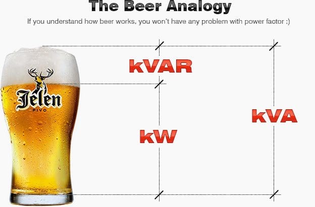
    Let’s say it’s friday evening, and you are with your friends at your favorite pub after really hot day. You order up a big mug of your favorite beer for you and for your friends. The thirst-quenching portion of your beer is represented by KW (the big pic on top).

    Unfortunately, life isn’t perfect. Along with your ale comes a little bit of foam. (And let’s face it…that foam just doesn’t quench your thirst.) This foam is represented by KVAR.

    The total contents of your mug, KVA, is this summation of KW (the beer) and KVAR (the foam).

    So, now that we understand some basic terms, we are ready to learn about power factor:

    Power Factor (P.F.) is the ratio of Working Power to Apparent Power.

    Power factor formula

    Looking at our beer mug analogy above, power factor would be the ratio of beer (KW) to beer plus foam (KVA).

    Power factor formula - Analogy with beer mug

    Thus, for a given KVA:

    1. The more foam you have (the higher the percentage of KVAR), the lower your ratio of KW (beer) to KVA (beer plus foam). Thus, the lower your power factor.
    2. The less foam you have (the lower the percentage of KVAR), the higher your ratio of KW (beer) to KVA (beer plus foam). In fact, as your foam (or KVAR) approaches zero, your power factor approaches 1.0.

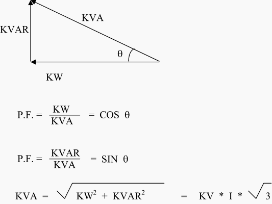
    Our beer mug analogy is a bit simplistic. In reality, when we calculate KVA, we must determine the “vectorial summation” of KVAR and KW. Therefore, we must go one step further and look at the angle between these vectors.


    Power Triangle

    The “Power Triangle” illustrates this relationship between KW, KVA, KVAR,  and Power Factor:

    Power Triangle

    Note that in an ideal world looking at the beer mug analogy:

    1. KVAR would be very small (foam would be approaching zero)
    2. KW and KVA would be almost equal (more beer; less foam)

    There are dosen of tools and technical articles/guides published at EEP that can help you to understand power factor and its controlling. Hope these can help:

    Resource: powerstudies.com

    Purpose of High Voltage Circuit Switchers

    $
    0
    0
    Vertical interrupter circuit switcher without integral disconnect switch

    Vertical interrupter circuit switcher without integral disconnect switch (Figure 2)

    Three-phase Interruption and Protection

    Circuit switchers have been developed to overcome some of the limitations of fusing for substation power transformers. Circuit switchers have SF6 gas interrupters and are designed to provide three-phase interruption (solving the unbalanced voltage considerations) and to provide protection for transient overvoltages and overloads at a competitive cost between the costs of power fuses and circuit breakers.

    Additionally they can provide protection from power transformer faults based on differential, sudden pressure, and overcurrent relay schemes as well as critical operating constraints such as for low oil level, high oil or winding temperature, pressure relief device operation, etc.

    The earliest circuit switchers were designed and supplied as a combination of a circuit breaking interrupter and an in-series isolating disconnect switch. These earliest models (see Fig. 1) had multiple interrupter gaps per phase on above 69 kV interrupters and grading resistors, thus the necessity for the in-series disconnect switch.

    Later models have been designed with improved interrupters that have reduced the number of gaps required for successful performance to a single gap per phase, thus eliminating the necessity of the disconnect switch blade in series with the interrupter.

    Multiple interrupter gap per phase circuit switcher

    Figure 1 - Multiple interrupter gap per phase circuit switcher


    Circuit switchers are now available in vertical interrupter design (see Fig 2 – picture above) or horizontal interrupter design configurations with (see Figure 3) or without (see Figure 4) an integral disconnect switch.

    The earliest circuit switchers had a 4 kA symmetrical primary fault current interrupting capability, but subsequent design improvements over the years have produced circuit switchers capable of 8, 10, 12, 16, 20, 25, 31.5, and 40 kA symmetrical primary fault current interrupting, with the highest of these interrupting values being on par with circuit breaker capabilities.

    Horizontal interrupter circuit switcher

    Figure 3 - Horizontal interrupter circuit switcher with integral vertical break disconnect switch.


    Horizontal interrupter line switchers provide load breaking, loop splitting, and line dropping capabilities for your most critical line switching applications. Additional applications include transformer magnetizing current interrupting and cable switching.

    All circuit making and breaking operations are accomplished in SF6 gas, eliminating open air arcs.

    Horizontal interrupter circuit switcher without integral disconnect switch

    Figure 4 - Horizontal interrupter circuit switcher without integral disconnect switch


    The interrupting speeds of circuit switchers have also been improved from their initial 8 cycle interrupting time to 6 to 5 to 3 cycles, with the 3 cycle offering the same speed as the most commonly available circuit breaker interrupting time.

    Different model types, configurations, and vintages have different interrupting ratings and interrupting speeds.

    Circuit switchers have been developed and furnished for applications involving protection of:

    1. Power transformers
    2. Lines,
    3. Cables
    4. Capacitor banks, and
    5. Line connected or tertiary connected shunt reactors.

    Circuit switchers can also be employed in specialty applications such as series capacitor bypassing and for load= line =loop interrupting applications where fault-closing capabilit y is required (as fault-closing capability is not a feature inherent in disconnect switch mounted load =line =loop interrupters or in the disconnect switches these interrupters are mounted on).


    Key Advantages

    These are the main advantages of HV Circuit Switchers:

    1. Makes and breaks circuit in SF6
    2. Ships fully assembled to minimize installation time
    3. Local visual indication of gas pressure provided by color coded temperature compensated gas gauge
    4. Common gas system with gas density switch with low pressure alarm and low pressure lockout for remote status monitoring
    5. Compact design and easy installation makes this an ideal switcher for replacement of power fuses to achieve 3 phase protection
    6. Straight forward mechanical design insures long life, repeatable operation

    Rated Duty Cycle
    O – 0.3 sec – CO – 15 sec –CO

    Resource: Electric Power Engineering Handbook – Leonard L. Grigsby (Get this book from Amazon)

    How to Select Right Frequency Converter for Variable Speed Drive (VSD)?

    $
    0
    0
    Danfoss inverters for application brackish water

    Application: Brackish water - 3 APP 2,2 equiped with Danfoss inverters for flexible use at universety. Place of installation: UK


    Selecting of a frequency converter for variable speed drives requires a lot of experience. If the experience is not available, it is often useful to visit either a reference plant with similar applications, or exhibitions or trade shows.


    Checklist

    The following is a brief checklist of points that should be considered:

    1. Details of the machine to be controlled
    2. Environmental details
    3. Mains
    4. Maintenance, operation, personnel
    5. Financial criteria
    6. Protective measures for operators/converter/motor
    7. Standards/regulations
    8. Environmental considerations
    9. Also important…

    VLT Drives Applications (VIDEOS)

    Some of the interesting applications done with Danfoss VLT drives:

    1. VLT drives in large desalination plant
    2. VLT drives control cooling tower fans
    3. VLT control optimizes spindle speed in Indian textile factory
    4. VLT frequency converters drive bagage handling system
    5. VLT Drives Save 78% Energy in Chester Zoo

    1. Details of the machine to be controlled

    1. Required plant/machine characteristics
    2. Torque characteristics, stalling torque, acceleration torque
    3. Speed control range, cooling
    4. Power consumption of the converter and the motor
    5. Operating quadrants
    6. Slip compensation (dynamic)
    7. Required ramp-up and ramp-down times
    8. Required braking times, brake operating time
    9. Direct drives, gears, transmission components, moment of mass inertia
    10. Synchronisation with other drives
    11. Operating time, controls
    12. Computer linkage, interfaces, visualisation
    13. Design and protection type
    14. Possibility of integrating decentral intelligence in the frequency converter

    Go up to the Checklist ↑


    2. Environmental details

    1. Installation height, ambient temperature
    2. Cooling requirements, cooling options
    3. Climatic conditions, such as humidity, water, dirt, dustgas-es
    4. Special regulations, e.g. for mining, the chemical industrythe ship building industry, food technology
    5. Acoustic noise

    Go up to the Checklist ↑


    3. Mains

    1. Mains voltage, voltage fluctuations
    2. Mains performance
    3. Mains frequency fluctuations
    4. Mains interference
    5. Short-circuit and overvoltage protection
    6. Mains drop-out

    Go up to the Checklist ↑


    4. Maintenance, operation, personnel

    1. Training and instruction of operators
    2. Maintenance
    3. Spare parts/spare units

    Go up to the Checklist ↑


    5. Financial criteria

    1. Purchase costs (components)
    2. Space requirement, integrated installation, design
    3. Installation costs
    4. Commissioning of the system
    5. Set-up costs
    6. Operating costs
    7. Efficiency of the system (frequency converter and machine)
    8. Reactive power requirement and compensation for harmonic loads
    9. Product lifetime

    Go up to the Checklist ↑


    6. Protective measures for operators/converter/motor

    1. Galvanic isolation in accordance with PELV
    2. Phase drop-out
    3. Switching at the converter output
    4. Earth and short-circuit protection
    5. Motor coils to reduce voltage rise times
    6. Electronic thermal monitoring and connection of thermistors

    Go up to the Checklist ↑


    7. Standards/regulations

    1. National DIN, BS, UL, CSA, VDE, European EN
    2.  International IEC, CE, etc.

    Go up to the Checklist ↑


    8. Environmental considerations

    1. Ability to recycle the product
    2. Manufacturing practice
    3. Energy saving factors

    Go up to the Checklist ↑

    Also important…

    Using this checklist a frequency converter can be selected which covers most of the items as standard, but you should also double check whether:

    • The converter has mains or intermediate circuit chokes in order to greatly reduce mains interference
    • A RFI filter for class A or B is standard or has to be purchased separately
    • Motor derating is required if a frequency converter is used
    • The converter itself is protected against earth and short-circuit
    • The converter reacts adequately in a fault situation.

    Go up to the Checklist ↑

    VLT Drives Applications (VIDEOS)

    1. VLT drives in large desalination plant

    Cant see this video? Click here to watch it on Youtube.

    Go up to the Applications ↑


    2. VLT drives control cooling tower fans

    Cant see this video? Click here to watch it on Youtube.

    Go up to the Applications ↑


    3. VLT control optimizes spindle speed in Indian textile factory

    Cant see this video? Click here to watch it on Youtube.

    Go up to the Applications ↑


    4. LT frequency converters drive bagage handling system

    Cant see this video? Click here to watch it on Youtube.

    Go up to the Applications ↑


    5. LT Drives Save 78% Energy in Chester Zoo

    Cant see this video? Click here to watch it on Youtube.

    Go up to the Applications ↑

    Resource: Fact Worth Knowing About Frequency Converters – Danfoss

    Stator Overheating Protection

    $
    0
    0
    Stator Overheating Protection

    Stator Overheating Protection (on photo bottom of the Motor Stator Winding; by electrical-forensics.com)

    Overheating

    All motors need protection against overheating resulting from overload, stalled rotor, or unbalanced stator currents.

    For complete protection, three-phase motors should have an overload element in each phase. This is because an open circuit in the supply to the power transformer feeding a motor will cause twice as much current to flow in one phase of the motor as in either of the other two phases, as shown in Figure 1.

    Consequently, to be sure that there will be an overload element in the most heavily loaded phase no matter which power-transformer phase is open-circuited, one should provide overload elements in all three phases.

    In spite of the desirability of overload elements in all three phases, motors rated about 1500 hp and below are generally provided with elements in only two phases, on the assumption that the open-phase condition will be detected and corrected before any motor can overheat.

    Illustrating the need for overcurrent protection in each phase

    Figure 1 - Illustrating the need for overcurrent protection in each phase


    Single-phase motors require an overload element in only one of the two conductors.


    Motors Other than Essential Service

    Except for some essential-service motors, whose protection will be discussed later, it is the practice for motors rated less than about 1500 hp to provide either replica-type thermal-overload relays or long-time inverse-time-overcurrent relays or direct-acting tripping devices to disconnect a motor from its source of supply in the event of overload.

    Which type of relay to use is largely a matter of personal preference.

    Other things being equal, the replica type will generally provide the best protection because, as shown in Figure 2, its time-current characteristic more nearly matches the heating characteristic of a motor over the full range of overcurrent; also, it may take into account the heating effect of the load on the motor before the overload condition occurred.

    Typical motor-heating and protective-relay characteristics

    Figure 2 - Typical motor-heating and protective-relay characteristics. A, motor; B, replica relay; C, inverse-time relay.


    The inverse-time-overcurrent relay will tend to “overprotect” at low currents and to “under protect” at high currents, as shown in Figure 2.

    Inverse-Time Overcurrent type e ICM 21 - ABB

    Inverse-Time Overcurrent type e ICM 21 - ABB

    However, the overcurrent relay is very easy to adjust and test, and it is self-reset. For continuous-rated motors without service factor or short-time overload ratings, the protective relays or devices should be adjusted to trip at not more than about 115% of rated motor current.

    For motors with 115% service factor, tripping should occur at not more than about 125% of rated motor current. For motors with special short-time overload ratings, or with other service factors, the motor characteristic will determine the required tripping characteristic, but the tripping current should not exceed about 140% of rated motor current.

    The manufacturer’s recommendations should be obtained in each case.

    The overload relays will also provide protection in the event of phase-to-phase short circuits, and in practice one set of such relays serves for both purposes wherever possible.

    A survey of the practice of a number of power companies45 showed that a single set of longtime inverse-time-overcurrent relays, adjusted to pick up at 125% to 150% of rated motor current, is used for combined short-circuit and overload protection of non-essential auxiliary motors; they are supplemented by instantaneous overcurrent relays adjusted as already described.

    Such inverse-time overload relays must withstand short-circuit currents without damage for as long as it takes to trip the breaker. Also the minimum requirements as to the number of relays or devices for either function must be fulfilled.

    Motors rated higher than about 1500 hp are generally provided with resistance temperature detectors embedded in the stator slots between the windings. If such temperature detectors are provided, a single relay operating from these detectors is used instead of the replica-type or inverse-time-overcurrent relays.

    Also, current-balance relays capable of operating on about 25% or less unbalance between the phase currents should be supplied. If the motor does not have resistance temperature detectors, but is provided with current-balance relays, a single replica-type thermal overload relay may be substitutedfor the resistance-temperature-detector relay.

    Specially cooled or ventilated motors may require other types of protective equipment than those recommended here. For such motors, the manufacturer’s recommendations should be obtained.

    Reference 50 gives more useful information on the subject of industrial-motor protection.


    Essential-Service Motors

    The protection recommended for some essential-service motors is based on minimizing the possibility of unnecessarily tripping the motor, even though such practice may sometimes endanger the motor. In other words, long-time inverse-time overcurrent relays are provided for all motor ratings, but they merely control an alarm and leave tripping in the control of an operator.

    Then, for motors that can suffer locked rotor, supplementary instantaneous overcurrent relays, adjusted to pick up at about 200% to 300% of rated motor current are used, and their contacts are connected in series with the contacts of the inverse time-overcurrent relays to trip the motor breaker automatically.

    The instantaneous relays should be of the high-reset type to be sure that they will reset when the current returns to normal after the starting inrush has subsided. The protection provided by this type of equipment is illustrated in Figure 3.

    Protection characteristic for essential-service motors

    Figure 3 - Protection characteristic for essential-service motors. A, motor; B, inverse-time relay; C, instanteneous relay.


    For essential-service motors for which automatic tripping is desired in addition to the alarm for overloads between about 115% of rated current and the pickup of the instantaneous overcurrent relays, thermal relays of either the replica type or the resistance temperature-detector type should be used, depending on the size of the motor.

    Such relays permit operation for overloads as far as possible beyond the point where the alarm will be sounded, but without damaging the motor to the extent that it must be repaired before it can be used again.

    Resource: The ART & SCIENCE of protective relaying – C. Russell Mason

    Wind power applications, Grid connected or not?

    $
    0
    0
    Wind power applications, Grid connected or not?

    Wind power applications, Grid connected or not? (on photo: The wind turbines, each with a rated power output of 3.2 megawatts (MW) and a hub height of 143 metres, are intended for the Poysdorf-Wilfersdorf III wind farm in the north-east of Austria.)


    There are perhaps four distinct categories of wind power which should be discussed.

    These are:

    1. Small, non-grid connected
    2. Small, grid connected
    3. Large, non-grid connected
    4. Large, grid connected

    By small, we mean a size appropriate for an individual to own, up to a few tens of kilowatts. Large refers to utility scale.


    Small, Non-Grid Connected

    Home wind turbines

    Home wind turbines - designed for ease of use, they are smooth and quiet.


    If one wants electricity in a location not serviced by a utility, one of the options is a wind turbine, with batteries to level out supply and demand. This might be a your home, a remote antenna and transmitter site, or a Third-World village.

    The costs will be high, on the order of $0.50/kWh, but if the total energy usage is small, this might be acceptable.

    The alternatives, photovoltaics, microhydro, and diesel generators, are not cheap either, so a careful economic study needs to be done for each situation.

    Go to top ↑


    Small, Grid Connected

    Small wind turbine - Grid connected

    Small wind turbine - Grid connected (Horizontal-axis turbine designed and installed in San Francisco)


    The small, grid connected turbine is usually not economically feasible. The cost of wind-generated electricity is less because the utility is used for storage rather than a battery bank, but is still not competitive.

    In order for the small, grid connected turbine to have any hope of financial breakeven, the turbine owner needs to get something close to the retail price for the wind-generated electricity.

    One way this is done is for the owner to have an arrangement with the utility called net metering. With this system, the meter runs backward when the turbine is generating more than the owner is consuming at the moment.

    The owner pays a monthly charge for the wires to his home, but it is conceivable that the utility will sometimes write a check to the owner at the end of the month, rather than the other way around.

    The utilities do not like this arrangement. They want to buy at wholesale and sell at retail.

    They feel it is unfair to be used as a storage system without remuneration.

    For most of the twentieth century, utilities simply refused to connect the grid to wind turbines. The utility had the right to generate electricity in a given service territory, and they would not tolerate competition. Then a law was passed that utilities had to hook up wind turbines and pay them the avoided cost for energy.

    Unless the state mandated net metering, the utility typically required the installation of a second meter, one measuring energy consumption by the home and the other energy production by the turbine.

    The owner would pay the regular retail rate, and the utility would pay their estimate of avoided cost, usually the fuel cost of some base load generator.

    The owner might pay $0.08 to $0.15 per kWh, and receive $0.02 per kWh for the wind-generated electricity. This was far from enough to eco-nomically justify a wind turbine, and had the effect of killing the small wind turbine business.

    Go to top ↑


    Large, Non-Grid Connected

    Large, non-grid connected wind turbines installed on mountain

    Large, non-grid connected wind turbines installed on mountain


    These machines would be installed on islands, high mountains or native villages in the far north where it is virtually impossible to connect to a large grid. Such places are typically supplied by diesel generators, and have a substantial cost just for the imported fuel.

    One or more wind turbines would be installed in parallel with the diesel generators, and act as fuel savers when the wind was blowing.

    This concept has been studied carefully and appears to be quite feasible technically. One would expect the market to develop after a few turbines have been shown to work for an extended period in hostile environments.

    It would be helpful if the diesel maintenance companies would also carry a line of wind turbines so the people in remote locations would not need to teach another group of maintenance people about the realities of life at places far away from the nearest hardware store.

    Go to top ↑


    Large, Grid Connected

    Large, Grid Connected Wind turbines

    In Schlalach-Mühlenfließ, a small town in the German region of Brandenburg, 16 gigantic wind turbines stretch into the air. Every tower has huge, rotating blades and a height of close to 180 meters.


    We might ask if the utilities should be forced to buy wind-generated electricity from these small machines at a premium price which reflects their environmental value.

    Many have argued this over the years.

    A better question might be whether the small or the large turbines will result in a lower net cost to society.

    Given that we want the environmental benefits of wind generation, should we get the electricity from the wind with many thousands of individually owned small turbines, or should we use a much smaller number of utility-scale machines?

    If we could make the argument that a dollar spent on wind turbines is a dollar not spent on hospitals, schools, and the like, then it follows that wind turbines should be as efficient as possible. Economies of scale and costs of operation and maintenance are such that the small, grid connected turbine will always need to receive substantially more per kilowatt hour than the utility-scale turbines in order to break even.

    There is obviously a niche market for turbines that are not connected to the grid, but small, grid connected turbines will probably not develop a thriving market. Most of the action will be from the utility-scale machines.

    Sizes of these turbines have been increasing rapidly. Turbines with ratings near 1 MW are now common, with prototypes of 2 MW and more being tested. This is still small compared to the needs of a utility, so clusters of turbines are placed together to form wind power plants with total ratings of 10 to 100 MW.

    Go to top ↑

    Resource: Electric Power Generation: Non-Conventional Methods – Saifur Rahman Virginia Tech


    Few Words About Frequency Converters

    $
    0
    0
    Few Words About Frequency Converters

    Few Words About Frequency Converters (on photo cabinet with Danfoss FC302 frequency converters)

    Introduction

    Since the late 1960’s, frequency converters have undergone extremely rapid changes, largely as a result of the development of microprocessor and semi-conductor technologies and their reduction in prices. However, the basic principles of frequency converters remains the same.

    Frequency converters can be divided into four main components:

    Simplified frequency converter

    Figure 1 - Simplified frequency converter

    1. Rectifier

    The rectifier, which is connected to a single/three-phase AC mains supply and generates a pulsating DC voltage. There are two basic types of rectifiers – controlled and uncontrolled.


    2. Intermediate circuit

    The intermediate circuit. There are three types:

    1. One, which converts the rectifier voltage into a direct current.
    2. One, which stabilises or smoothes the pulsating DC voltage and places it at the disposal of the inverter.
    3. One, which converts the constant DC voltage of the rectifier to a variable AC voltage.

    3. Inverter

    The inverter which generates the frequency of the motor voltage. Alternatively, some inverters may also convert the constant DC voltage into a variable AC voltage.


    Control circuit

    The control circuit electronics, which transmit signals to- and receive signals from the rectifier, the intermediate circuit and the inverter. The parts that are controlled in detail depends on the design of the individual frequency converter (see Figure 2).

    What all frequency converters have in common is that the control circuit uses signals to switch the inverter semi-conductors on or off. Frequency converters are divided according to the switching pattern that controls the supply voltage to the motor.

    In figure 2, which shows the different design /control principles:

    1. Is a controlled rectifier,
    2. Is an uncontrolled rectifier,
    3. Is a variable DC intermediate circuit,
    4. Is a constant DC voltage intermediate circuit,
    5. Is a variable DC intermediate circuit,
    6. Is a PAM inverter and
    7. PWM inverter.
    Different design / control principles of frequency converter

    Figure 2 - Different design / control principles of frequency converter


    Current Source Inverter: CSI
    (1 + 3 + 6)

    Pulse-amplitude-modulated converter: PAM
    (1 + 4 + 7) (2 + 5 + 7)

    Pulse-width-modulated converter: PWM/VVCplus
    (2 + 4 + 7)

    Direct converters, which do not have an intermediate circuit should also be briefly mentioned for completeness. These converters are used in the Mega-watt power range to generate alow-frequency supply directly from the 50 Hz mains and their maximum output frequency is about 30 Hz.

    Resource: Fact Worth Knowing About Frequency Converters – Danfoss

    VLT Drives in Wastewater Treatment Plant Applications

    $
    0
    0
    VLT Drives in Wastewater Treatment Plant Applications

    VLT Drives in Wastewater Treatment Plant Applications (on photo: Vienna’s Main Sewage Treatment Plant, Austria)


    The most common use of frequency converters is to drive sludge pumps, elevators, conveyers, aeration, chemical dosing, clarifiers, digesters, presses and centrifugal dewatering.


    Treatment steps

    Preliminary treatment

    In the beginning water is being pumped into the plant from the collection basin.

    Wastewater Supply

    Figure 1 - Wastewater Supply


    The frequency converter is using water level as input to control the speed (flow) of the pump.

    Removal of bigger solid particles out of wastewater is usually the first basic process in wastewater treatment, and we use it to prevent frequent flooding and overflows and jamming of cleaning device, to protect valves, pumps and pipes and to keep the rest of the process going normally.

    Bar screen

    Figure 2 - Bar screen


    Bigger pieces of wood, plastic, metal, rubber, textile and other waste materials out of wastewater is being removed by using bar screens.

    We can usually find two types of bar screens:

    1. Coarse sieve (rake) and
    2. Fine sieve.

    Coarse sieves have openings equal to or greater than 6 mm and generally protective role, while using a fine sieve, with openings smaller than 6 mm, and can achieve significant removal of suspended solids from the wastewater.

    The grid is usually made up of parallel rods, while the fine screen usually used wire cloth or perforated metal plate.

    Fine Sieves

    Figure 3 - Fine Sieves

    Wastewater treatment

    In the further process of wastewater treatment applications are similar installations for the treatment of drinking water.

    Primary treatment clarifier

    Figure 4 - Primary treatment clarifier


    First the floating organic and inorganic impurities are removed. We use drives in clarifiers with scrapers, chemical dosing in the process of coagulation and flocculation and the sludge removal pumps and various pumps to transfer treated water from one part of the plant to another.

    Deposition belongs to the sedimentation process group – the process of separating the solid and liquid phases under the influence of gravity. Deposition takes place in clarifiers.

    Colloids are very stable suspension of fine particles in water, and their size in range of 0,1 – 0,001 μm. Because such a small size of individual particles, colloidal suspensions are practically stable and appear as a “cloud” in the water.

    Colloidal suspended material cannot be removed using only filtration techniques. The separation is based on the processes of coagulation and flocculation (clarification).

    Mixer motors in process of coagulation and flocculation are driven with frequency converters, where the mixer speed in process of coagulation is determined by the amount of chemicals that is added in coagulation process. In flocculation process mixer speed is determined by the amount of incoming wastewater (flow) because if the mixing speed is to low flocculation will not be possible, however if the mixing speed is too fast, floccules that are already created will dissolve.

    Outgoing sludge pump is controlled by frequency converter that has clarifier water level as input. The advantage of using frequency converters is in reducing the sludge level, preventing „Rathole” effect in sludge pump, and preventing overload and underload of the pump.

    Aerator and clarifier in secondary treatment

    Figure 5 - Aerator and clarifier in secondary treatment


    Underwater blower aeration is one of the most efficient ways to get proper aeration according water characteristics. Blower speed is being controlled by frequency converter. The input signal are flow (or pressure), the amount of oxygen and PH value of the water.

    Blower speed reduction leads to significant energy savings since it has variable torque, and it is one of the biggest energy consumers in wastewater plant.

    Filtration can be performed in open or closed, quick or gravity sand filters.

    Filter plant

    Figure 6 - Filter plant


    Beside standard supply water applications and chemical dosing, very important application is filter backwash pump.

    When the backwash cycle is initiated, the feed pump receives a 4-20 mA signal from differential level transmitters monitoring the influent and effluent sides, and determines the amount of backwash water required for cleaning. This way we minimize filter media loss by controlling the discharge velocities of the pump.

    The backwash water from the collection sump is transferred back to the head of the plant. Drives on the transfer pump enable efficient transferring of the backwash water by operating at variable speeds to keep low water levels.


    Sludge treatment

    Mixing pump at anaerobic digester

    Figure 7 - Mixing pump at anaerobic digester

    Digester is the most important part of sludge treatment. There are two types of digesters: anaerobic and aerobic digester.

    Anaerobic digester is closed concrete chamber, where condition is controlled, without air, organic material is processed into methane and carbon dioxide using intermittent gas mixing system. As a result you can get natural fertilizer and biogas as fuel. The most common use of frequency converters to control the pressure of supply sludge pumps, control of circulation pumps that provide proper positioning of hot water, which is part of the technological process.

    In aerobic digester sludge shall be air supplied until it comes to the decomposition.

    Aerobic digester

    Figure 8 - Aerobic digester


    Frequency converters control aeration blowers, oxigene sensors give them input signal so the air supply is regulated.

    Centrifugal dewatering motors are also controlled by frequency converters.

    Centrifugal sludge dewatering

    Figure 9 - Centrifugal sludge dewatering


    In this case we have 2-3 preset speed so the centrifuge is optimized due to sludge supply.

    Centrifugal dewatering motors can go up to 400kW and all posible speed ajustments can lead to significant energy savings.

    Dewatering can be done by the press, which consists of two elastic straps that are placed parallel to each other, between them there is sludge drying by pressure and shear force.

    Sludge dewatering press

    Figure 10 - Sludge dewatering press


    Frequency converters control the press motors according to the ammount of the sludge and its density. This way we can optimize dewatering process by speed ajustments.

    Follow the link for more details: http://www.danfoss.com/Solutions/World+of+Water/

    HV Instrument Current Transformers in T&D

    $
    0
    0
    HV Intrument Current Transformers in T&D

    HV Instrument Current Transformers in Transmission and Distribution Systems (on photo: Bus bar-type current transformer used together with transformer bushing, circuit breaker outlet bushing, switchgear bushing, and bus bar, for supplying measuring signal and protitective signal of current. - by Beijing Nobbel Electric Tech Develop Co., Ltd)

    Introduction

    Electrical measurements on a high-voltage transmission and distribution systems cannot be made practically or safely with direct contact to the power carrying conductors. Instead, the voltages and currents must be brought down to a safe and usable level that can be input into measuring instruments.

    This is the whole point task of an instrument transformers CTs and VTs.

    They provide replica voltages and currents scaled to more manageable levels. They also bring their replicas to a safe ground potential reference. The most common output range 0 – 5.0 A for currents based on their nominal inputs. Other ranges are used as well.

    The majority of these devices are iron core transformers.


    Current Transformers

    Current transformers (CTs) of all sizes and types find their way into substations to provide the current replicas for metering, controls, and protective relaying. Some will perform well for SA applications and some may be marginal.

    CT performance is characterized by:

    1. Turns ratio,
    2. Turns ratio error (ratio correction factor),
    3. Saturation voltage,
    4. Phase angle error, and
    5. Rated secondary circuit load (burden).

    CTs are often installed around power equipment bushings, as shown in Figure 1 below:

    Bushing current transformer installation

    Figure 1 - Bushing current transformer installation


    They are the most common types found in medium voltage and high voltage equipment. Bushing CTs are toroidal, having a single primary turn (the power conductor), which passes through their center. The current transformation ratio results from the number of turns wound on the core to make up the primary and secondary.

    Lower voltage CTs are often a ‘‘wound’’ construction with both a multiturn primary and secondary winding around their ‘‘E-form’’ or ‘‘shell form’’ core.

    Their ratio is the number of secondary turns divided by the number of primary turns. CT secondary windings are often tapped to provide multiple turns ratios. The core cross-sectional area, diameter, and magnetic properties determine the CT’s performance.

    As the CT is operated over its nominal current ranges, its deviations from specified turns ratio are characterized by its ratio correction curve sometimes provided by the manufacturer. At low currents, the exciting current of the iron core causes ratio errors that are predominant until sufficient primary magnetic flux overcomes the effects of core magnetizing.

    Thus, watt or var measurements made at very low load may be substantially in error both from ratio error and phase shift. Exciting current errors are a function of individual CT construction. They are generally higher for protection CTs than revenue metering CTs by design.

    Revenue metering CTs are designed with core cross sections chosen to minimize exciting current effects and their cores are allowed to saturate at fault currents. Protection CTs use larger cores as high current saturation must be avoided for the CT to faithfully reproduce high currents for fault sensing.

    The exciting current of the larger core at low primary current is not considered important for protection but can be a problem for measuring low currents. Core size and magnetic properties determine the ability of CTs to develop voltage to drive secondary current through the circuit load impedance (burden).

    This is an important consideration when adding SA IEDs or transducers to existing metering CT circuits, as added burden can affect accuracy. The added burden of SA devices is less likely to create metering problems with protection CTs at load levels, but could have undesirable effects on protective relaying at fault levels. In either case, CT burdens are an important consideration in the design.

    Experience with both protection and metering CTs wound on modern high silicon steel cores has shown, however, that both perform comparably once the operating current sufficiently exceeds the exciting current if secondary burden is kept low.

    Bushing Type Current Transformer with Protection Box

    Bushing Type Current Transformer with Protection Box


    CT secondary windings are generally uncommitted.

    They can be connected in any number of configurations so long as they have a safety ground connection to prevent the windings from drifting toward the primary voltage. It is common practice to connect CTs in parallel so that their current contribution can be summed to produce a new current such as one representing a line current where the line has two circuit breaker connections such as in a ‘‘breaker-and-a-half ’’ configuration.

    CTs are an expensive piece of equipment and replacing them to meet new measuring performance requirements is usually cost prohibitive.

    However, new technology has developed, which makes it possible for an IED to compensate for CT performance limitations.

    This technology allows the IED to ‘‘learn’’ the properties of the CT and correct for ratio and phase angle errors over the CT’s operating range. Thus, a CT designed to feed protection devices can be used to feed revenue measuring IEDs and meet the requirements of IEEE Standard C57.13.

    Occasions arise where it is necessary to obtain current from more than one source by summing currents with auxiliary CTs.

    There are also occasions where auxiliary CTs are needed to change the overall ratio or shift phase relationships from a source from a wye to a delta or vice versa to suit a particular measuring scheme. These requirements can be met satisfactorily only if the auxiliaries used are adequate. If the core size is too small to drive the added circuit burden, the auxiliaries will introduce excessive ratio and phase angle errors that will degrade measurement accuracy.

    Using auxiliary transformer must be approached with caution.

    Resource: Automation and the Substation – James W. Evans, The St. Claire Group, LLC

    Purpose of Miniature Circuit Breakers (MCBs)

    $
    0
    0
    Using Miniature Circuit Breaker (MCB)

    Using Miniature Circuit Breaker (MCB) - (on photo: Acti 9, the new DIN rail miniature circuit breaker (MCB) by Schneider Electric)

    Principle of operation and design

    Miniature circuit breakers (MCB) are primarily designed to protect cables and lines against overload (thermal) and short-circuit (electromagnetic). They thus care for protecting this electrical equipment against excessive temperature rises and destruction in the event of a short-circuit.

    Miniature circuit breakers are used in distribution networks in homes and in industrial applications.

    They meet the requirements for different applications by various designs and with the aid of a comprehensive range of accessories (for example auxiliary and signal contacts etc.).

    The structural shape of all line protection switches is similar. Certain dimensions are defined by the installation standards (in some cases national). The major differences lie in the widths (for example 12.5 and 17.5 mm) or depths (for example 68 and 92.5 mm).

    The breaking capacity is one of the factors that determine the size.


    Standards, tripping characteristics and rated switching capacity

    MCB’s are subject to international and national norms. The design and test requirements are defined in the standard IEC 60898.

    For the various applications three trip characteristics B, C and D are defined in IEC 60898 (Figure 1):

    The tripping characteristics B, C and D under IEC 60898 are distinguished by the trip level of the short-circuit trigger

    Figure 1 - The tripping characteristics B, C and D under IEC 60898 are distinguished by the trip level of the short-circuit trigger


    The tripping characteristics B, C and D under IEC 60898 are distinguished by the trip level of the short-circuit trigger

    • Trip characteristic B is the standard characteristic for wall outlet circuits in domestic and utility buildings (I> ≥3 … 5*Ie)
    • Trip characteristic C is advantageous when using electrical equipment with higher inrush currents as for example of lamps and motors (I> ≥5 … 10*Ie)
    • Trip characteristic D is adapted to electrical equipment that can produce strong current surges such as transformers, electromagnetic valves or capacitors (I> ≥10 … 20*Ie)
    AC miniature circuit breakers are normally suitable for single-phase and three-phase supplies up to a rated voltage of 240/415V and AC-DC MCB’s additionally for direct voltage supplies up to rated voltages of 125 V, 220 V or 440 V depending on the number of poles.

    In addition to the quality of releasing according to the tripping characteristic, a key feature of MCB’s is their rated switching capacity. They are assigned to switching capacity classes, which indicate the maximum size of short-circuit current that can be handled.

    Standard values under IEC 60898 are 1500, 3000, 4500, 6000, 10000, 20000 and 25000 A.

    When selecting a MCB to protect cables and conductors, the permissible let-through-I2·t values for conductors must be respected. They may not be exceeded during clearing a short-circuit.

    Therefore the I2·t values in relation to the prospective short-circuit current are important characteristic of MCB’s.

    In some countries, miniature circuit breakers are classified according to the permissible I2·t values. According to the “Technical Connection Conditions” (TAB) of the German power utilities (EVU) for example only MCB’s with a rated switching capacity of at least 6000 A and the energy limitation Class 3 may be used for selectivity reasons in distribution boards of domestic and utility buildings behind the meter.

    For industrial applications a switching capacity of 10000 A (10 kA) is usually required.


    Installation of Miniature Circuit Breakers, safety clearances

    MCB’s as components of installation systems are usually designed so that compliance with safety clearance requirements is assured when arranged conform to the system structure.

    Circuit breakers can cope with very high currents at high voltages when breaking short-circuits.

    MCB Safety clearances

    Figure 2 - It is essential that the safety clearances are observed. No conductive parts may be located within the hatched zones such as metallic walls or uninsulated conductors.


    During the breaking process, the contact systems and arcing chambers consequently convert large amounts of power into heat energy.

    In addition to high temperature rises of components such as contacts, de-ion plates and walls of the contact chambers, the energy converted into an arc results in heating of the air in the contact system to several thousand degrees Celsius and hence to the formation of a conductive plasma. This plasma is usually emitted through blow-out openings to the outside and must not reach any conductive parts to prevent secondary short-circuits.

    For this season, safety clearances are specified for circuit breakers (Figure 2), within which no conductive parts – for example metallic walls or uninsulated conductors – may be located.

    Frequently additional insulation components (phase partition walls or covers; in some cases optional) are used. With some products, additional insulation of the connected conductors is required in accordance with manufacturer specifications.

    Non-compliance with the safety clearances can result in accidents with most severe consequences.


    Example: Acti 9 MCB (VIDEO)

    Cant see this video? Click here to watch it on Youtube.

    Resource: Allen Bradley – Low Voltage Switchgear and Controlgear

    Surge Protection for Frequency Converters

    $
    0
    0
    Schematic diagram of a frequency converter

    Figure 1 - Schematic diagram of a frequency converter


    In principle a frequency converter consists of a rectifier, a d.c. link converter, an inverter and of the control electronics (Figure 1 above).

    At the input of the inverter the single phase or interlinked, three-phase a.c. voltage is changed into a pulsating d.c. voltage and is pushed into the d.c. link converter that also serves as energy store (buffer). Capacitors in the d.c. link converter and the LC networks connected to earth in the a.c. line filter, can cause problems with the residual current devices (RCD) connected in series.

    The reason for this is often wrongly seen in the application of surge arresters.

    The problems, however, result from the short-term induction of fault currents by the frequency converter. These are sufficient to activate sensitive earth leakage circuit breakers (RCDs).

    A surge-proof RCD circuit breaker available for a tripping current IΔn = 30 mA and a min. discharge capability of 3 kA (8/20 μs) provides a remedy.

    EMC conforming shield connection of the motor supply line

    Figure 2 - EMC conforming shield connection of the motor supply line


    By the control electronics, the inverter delivers a clocked output voltage. The higher the clock frequency of the control electronics for the pulse-width-modulation, the more sinusoidal is the output voltage. With each cycle, a peak voltage is created that is superimposed on the curve of the fundamental frequency. This peak voltage reaches values of 1200 V and higher (according to the frequency converter).

    The better the simulation of the sine curve at the output, the better is the performance and control response of the motor. This means, however, that the voltage peaks appear at the output of the frequency converter more frequently.

    For choosing of surge arresters, the maximum continuous operating voltage Uc has to be taken into account.

    It specifies the maximum permissible operating voltage a surge protective device may be connected to. This means that surge protective devices with a correspondingly higher Uc are used at the output side of the frequency converter.

    This avoids faster ageing due to gradually heating of the surge protective device under normal operating conditions and the consequential voltage peaks. This heating of the arrester leads to a shorter service life and consequently to a disconnection of the surge protective device from the system to be protected.

    The voltage at the output of the frequency converter is variable and adjusted a little bit higher than the nominal voltage at the input. Often it is approx. + 5 % during continuous operation, in order to compensate the voltage drop at the connected line, for example.

    Structure of a frequency converter with SPD

    Figure 3 - Structure of a frequency converter with SPD


    Example with Dehn devices

    1 - DEHNguard S DG S 275
    2 – DEHNguard S DG S 600
    3 – BLITZDUCTOR XT

    Otherwise, one can simply say that the maximum voltage at the input of the frequency converter is equal to the maximum voltage at the output of the frequency converter.

    The high clock frequency at the output of the frequency converter generates fieldborne interferences and therefore, requires necessarily a shielded cabling so that adjacent systems are not disturbed.

    For shielding the motor power supply line, a bilateral shield earthing at the frequency converter and the drive motor has to be ensured. The large-surface contacting of the shield results from the EMC requirements.

    Advantageous is here the use of constant force springs (Figure 2).

    By means of intermeshed earth-termination systems, i.e. the earth-termination system the frequency converters and the drive motor are connected to, potential differences are reduced between the parts of the installation and thus equalising currents via the shield are avoided.

    Figure 3 shows the example of use of surge protective devices Type DEHNguard on the power supply side and type BLITZDUCTOR for 0 – 20 mA signals. The protective devices have to be individually adapted according to the interface.

    For the integration of the frequency converter into the building automation it is absolutely essential that all evaluation and communication interfaces are connected with surge protective devices in order to avoid system failures.

    Resource: Lightning-Protection-Guide – dehn.de

    Viewing all 1474 articles
    Browse latest View live