Quantcast
Channel: EEP – Electrical Engineering Portal
Viewing all 1475 articles
Browse latest View live

Purpose of Disconnect Switches In HV Substation

$
0
0
Purpose of Disconnect Switches In HV Substation

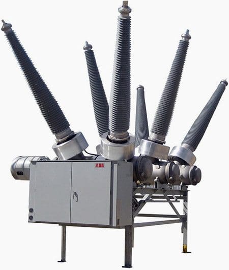
Purpose of Disconnect Switches In HV Substation (on photo: Siemens Goab switch)

Types and Characteristics

Switches may be of several types, the common characteristic is that none are designed to interrupt fault currents and the insulation or insulators associated with them must coordinate with the rest of the system and a BIL (Basic insulation level) capable of withstanding voltage surges.

In general, they consist of a conducting blade, hinged at one end, and a stationary contact on the other, both terminals mounted on suitable insulators that conform to the common insulator requirements of BIL coordination.

Almost every major line or equipment in a substation has associated with it a means of completely isolating it from other energized elements as a prudent means of insuring safety by preventing accidental energization. These simple switches, called disconnects, or disconnecting switches, are usually installed on both sides of the equipment or line upon which work is to be done.

They should not be operated while the circuit in which they are connected is energized, but only after the circuit is deenergized. As a further precaution, they may be opened by means of an insulated stick that helps the operator keep a distance from the switch.

Locking devices are sometimes provided to keep the disconnects from being opened accidentally or from being blown open during periods of heavy fault currents passing through them.

Although not designed to be closed to energize the line or equipment with which they are associated, in certain circumstances they may be closed, using special care to close them firmly and rapidly.

Disconnects may be singleblade units or multiple units operated together.

Air break switches have characteristics similar to disconnects, but have the stationary contacts equipped with arc suppressing devices that enable them to be opened while energized, but recognizing a limitation as to the current that may be safely interrupted.

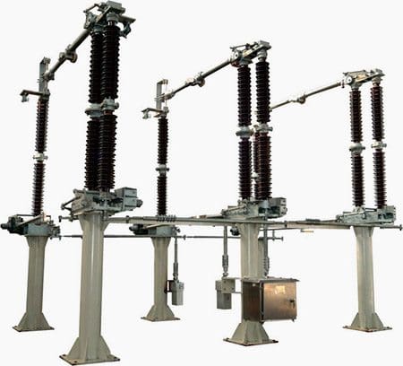
Transmission line disconnect switch

Transmission line disconnect switch (photo by Efrem Oshinsky @ Flickr)


The device may be a simple arcing horn which stretches the arc that may form until it cannot sustain itself.

Another type has a flexible “whip” attached to the stationary contact that continues the contact with the moving blade until a point is reached at which the whip snaps open very rapidly extinguishing any arc that may form.

Still another has an interrupting unit mounted at the free end of the switch blade and which suppresses the arc within the unit as the switch opens; the interrupting unit may contain a vacuum chamber, or a series of grids which cause the arc to break up into smaller ones and are more readily extinguished.

Both types function similarly as larger units do in circuit breakers.

Oil switches have the blade open from its contact under oil which suppresses any arc that may form. They have higher current breaking capacity than air break switches and are particularly suited for underground systems or where moisture or pollution make air switches impractical.

However, they (oil switches) are more expensive at first cost, to operate and to maintain.


138 kV Disconnects Switches (VIDEO)

Words from Robbie Oleksyn (author):

These 138kv disconnects switches have Joslyn current interrupters on them you can see them the grey tubes on the contact point, they didn’t work properly that was the issue. We were breaking parallel from two sources and when we were breaking it, the load transfer caused an arc and it didn’t extinguish itself the line tripped on over current unbalance.

Cant see this video? Click here to watch it on Youtube.


Disconnect Switch closing in on 138 kV (VIDEO)

Cant see this video? Click here to watch it on Youtube.

Resource: Power & Transmission Distribution – A. J. Pansini (get this book at Amazon)


D.M.C.R. Protection Relay for Oil Transformer

$
0
0
DMCR - Detection, Measurement and Control Relay for Hermetically Sealed Oil Transformer

DMCR - Detection, Measurement and Control Relay for Hermetically Sealed Oil Transformer

Content

  1. Dielectric fluid level is detected as low
  2. Overheating is detected
  3. Excess pressure is detected
  • Standards
  • Possibilities of D.M.C.R.:
    1. Oil level control and gas detection
    2. Pressure control
    3. Temperature control

    Introduction to D.M.C.R.

    The DMCR is a protection relay designed for the hermetically sealed oil immersed transformers without gas cushion. This device enables complete control of the tank’s internal parameters, i.e. pressure, temperature, oil level and gas detection.

    Fitted directly to the transformer cover, this relay ensures protection against internal faults, prolonged overvoltages and fire risks associated with the use of inflammable dielectric fluids.

    The accessory continuously monitors:

    1. Dielectric fluid level,
    2. Tank internal pressure,
    3. Dielectric fluid temperature at two different thresholds.

    To operate properly, the protection relay mustbe fully filled with fluid (level higher than the float visible in the transparent section of the unit). If this is not the case, check the instructions which appear inside each casing.

    To ensure optimum protection, the following action and adjustments are recommended:

    FindingRecommended adjustmentFault detectedAction to be taken
    Gas emitted or drop in levelLarge float at the topSerious faultDe-energize unit
    Pressure switch0.20 barSerious faultDe-energize unit
    Thermostat threshold 190°COvervoltagesActivate alarm
    Thermostat threshold 2100°COvervoltagesDe-energize unit

    There are two types of transformers:

    1. The air-cooled transformer, also called dry transformer
    2. The oil immersed transformer. The transformer is immersed in an oil-filled tank.
    The DMCR is a protection relay designed for the hermetically sealed oil immersed transformers without gas cushion. This device enables complete control of the tank’s internal parameters, i.e. pressure, temperature, oil level and gas detection.

    Go to Content ↑


    Faults detected on live transformer unit

    1. Dielectric fluid level is detected as low

    The protection relay is empty and the large float is at the bottom.

    May be due to:

    1.1 Air entering

    There must be a dielectric fluid leak and thus oily stains should be visible on the ground. Accurately localise the fault, carry out repair, then recheck the level with the body of fluid at a temperature of 20°C, before switching the unit live again.

    1.2 Internal gas emission

    Gas should be sampled using a syringe and then analysed.

    Whilst awaiting results, under no circumstances should the transformer be switched live again because a risk of total destruction exists.

    Go to Content ↑


    2. Overheating is detected

    This may be due to:

    1. Improper cooling of the transformer (insufficient air flow around unit or plan-troom ventilation),
    2. Continuous overvoltage.

    Go to Content ↑


    3. Excess pressure is detected

    This may be due to:

    1. Overheating
    2. Internal gas emission
    3. Topping up of dielectric fluid with the body of fluid below 20°C; drain the over-flow with the transformer de-energised and the dielectric fluid at 20°C.

    Go to Content ↑

    Standards

    This protection relay has been designed according to the European standard EN 50216-3, specification which came into action on the 5th of June 2002.

    This standard applies to protection relays for hermetically sealed oil immersed transformers, (in accordance with the EN 60076 standard) and induction coils (in accordance with the EN 60289 standard) without gas cushion for an indoor or outdoor use.

    The DMCR relay is an IDEF Systemes design, made in France. It has two French and one European patents.

    DMCR relay dimensions

    DMCR relay dimensions

    Go to Content ↑

    Possibilities of D.M.C.R.

    1. Oil level control and gas detection

    The DMCR enables to control both the oil level and the presence of gas inside the transformer’s tank. The DMCR body is a small see-through tank fitted ontothe transformer’s tank.

    Should gas form inside the transformer, it will then accumulate inside the DMCR and cause the oil level to drop.

    Visual information

    The level drop is first visible through the lowering of the small red float inside the upper part of the DMCR, followed by the lowering of the main red float.

    The 360 degree visibility is a specifically designed and patented system.

    Electrical information

    A circular magnet is fitted in the main float and it acts upon a magnetic changeover contact (REED switch) sitting inside the brass tube that runs through the float. The lowering of the float triggers the activation of an electrical contact, through the magnet’s motion.

    A bleeding system facilitates gas collection inside the relay so that one can analyze it and understand the reason for its presence. The bleeding system has a male G1/8’’ thread, accordingto the standard.

    For the oil level and gas detection control, the contacts have been chosen in order to use the REED switch’s working contact when the float is in a high position. This means that, in such a position, i.e. with a normal oil level and therefore normal conditions of use, the contact has already switched.

    This is a positive safety system. With this method, any potential damage to the switch is immediately spotted.

    The DMCR below is filled in with oil: the main float and the secondary float are both in high position.

    The DMCR - Oil level control and gas detection

    The DMCR - Oil level control and gas detection


    Go to Content ↑


    2. Pressure control

    Pressure inside a transformer’s tank can increase significantly when:

    1. There is a temperature rise due to the transformer charge: oil expands and pressure increases
    2. An internal short-circuit occurs and provokes an oil temperature rise.

    An adjustable pressure captor detects overpressure in the transformer’s tank. It features a changeover contact actuated by a soft membrane which deforms under pressure.

    The DMCRs pressure captor

    The DMCRs pressure captor is accessible from above, once the top removed


    Go to Content ↑


    3. Temperature control

    Visual check:

    A needle thermometer indicates the temperature inside the transformer.

    Electrical check

    Two identical adjustable thermostats detect potential over-heating inside the transformer.

    The thermostats feature a changeover contact actuated bya diaphragm linked by a capillary tube to a temperature probe sitting deep inside the central brass tube, which is immersed in the transformer’s tank. The capillary tube and probe are filled in with a liquid which expands proportionally to the temperature surrounding the probe.

    The ALARM thermostat detects a primary temperature threshold.

    The TRIPPING thermostat detects a secondary temperature threshold, superior to the first.

    DMCR - Tripping and alarm treshold settings

    DMCR - Tripping and alarm treshold settings


    Go to Content ↑


    Resources:
    • MINERA Transformer Installation guide – Schneider Electric
    • DMCR relay – IDEF Systems

    Underground Residential Distribution Layouts

    $
    0
    0
    Underground Residential Distribution Layouts

    Underground Residential Distribution Layouts

    Underground Construction

    Where general appearance, economics, congestion, or maintenance conditions make overhead construction inadvisable, underground construction is specified.

    While overhead lines have been ordinarily considered to be less expensive and easier to maintain, developments in underground cables and construction practices have narrowed the cost gap to the point where such systems are competitive in urban and suburban residential installations, which constitute the bulk of the distribution systems.

    The conductors used underground (see Figure 1) are insulated for their full length and several of them may be combined under one outer protective covering. The whole assembly is called an electric cable.

    Underground cable

    Figure 1 - Underground cable

    These cables may be buried directly in the ground, or may be installed in ducts buried in the ground. Concrete or metal markers are often installed at intervals to show the location of the cables.

    In residential areas, such cables may be buried by themselves by means of a plow or machine digging a narrow furrow.

    In commercial or other congested areas, where maintenance repair or replacement of the cables may be difficult, conduits or ducts and manholes may be installed underground to contain the cable and other equipment.

    Figure 2 illustrates a typical underground setup of a conduit system.

    Preparing the installation of an underground conduit system

    Figure 2 - Preparing the installation of an underground conduit system

    Distribution Layouts

    Distribution circuits to residential areas are similar to overhead designs, except the installation is underground.

    Primary mains, with take-offs, are installed to which are connected the distribution transformers that supply secondary low-voltage (120-240 volt) service to the consumers.

    Two general patterns have developed, economy being the deciding factor in the selection:

    Using an area transformer

    One pattern has as the primary supply a distribution transformer which may feed two or more consumers via secondary mains and services (Figure 3).

    Underground residential layout using an area transformer

    Figure 3 - Underground residential layout using an area transformer

    Using Individual Transformers

    Second pattern has as the primary supply individual transformers feeding only one consumer (Figure 4).

    Underground residential layout using individual transformers

    Figure 4 - Underground residential layout using individual transformers


    No secondary mains are required here, and the service connection to the consumer may be practically eliminated by placing the transformer adjacent to the consumer’s service equipment.

    The primary supply is of the radial type; that is, the feeders supplying a territory “radiate” from their substation source, much as the spokes of a wheel.

    Similarly, as is done in overhead circuits, the spurs or laterals are connected to the primary main through fuses, so that a fault on these laterals will not cause an interruption to the entire feeder.

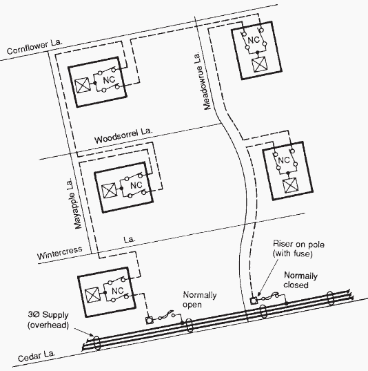
    However, as faults on underground systems may be more difficult to locate and take longer to repair than on overhead systems, the primary supplies may often be arranged in the pattern of an open-loop (Figure 5).

    Underground residential layout using open-loop construction

    Figure 5 - Underground residential layout using open-loop construction


    In this instance, the section of the primary on which the fault has occurred may be disconnected at both ends and service re-established by closing the loop at the point where it is normally left open.

    Such loops are not normally closed because a fault on a section of the feed may then cause the fuses at both ends to blow, leaving the entire area without supply and no knowledge of where the fault has occurred.

    Resource: Guide to Electrical Power Distribution Systems – Anthony J. Pansini (get it from Amazon)

    Power Measurement In a Three-Phase System

    $
    0
    0
    Power Measurement In a Three-Phase System

    Power Measurement In a Three-Phase System (on photo: Traditional power meter)

    Wattmeter

    Electrical power is measured with a wattmeter. A wattmeter consists of a current coil connected in series with load, while the other potential coil is connected parallel with load.

    Depending on the strength of each magnetic field movement, the pointer gets affected.

    The true or real power is directly shown in a wattmeter. In three-phase systems, power can be measured using several methods. For temporary measurements, a single wattmeter can be used.

    However, for permanent measurements, a three-phase wattmeter having two elements is used which indicates both balanced and unbalanced loads.

    For an unbalanced load, two wattmeters must be used as shown in the Figure 1.

    The total power is calculated by adding the measurement readings given by the two wattmeters. With this method, the power factor can also be obtained.

    When using the two-wattmeter method, it is important to note that the reading of one wattmeter should be reversed if the power factor of the system is less than 0.5. In such a case, the leads of one wattmeter may have to be reversed in order to get a positive reading. In the case of a power factor less than 0.5, the readings must be subtracted instead of being added.

    The power factor of the three-phase system, using the two-wattmeter method (W1 and W2) can be calculated as follows:

    Power factor of the three-phase system

    Since the sum and subtraction of readings are done to calculate total true power of a three-phase system, methods shown are not used practically in industry.

    Rather three-phase power analyzers are used which are more user-friendly.


    Power Factor Meter

    What’s common for Beer Mug and Power Factor? Learn. 

    It is similar to a wattmeter in principle, only two armature coils are provided with mountings, on a single shaft. They are 90° apart from each other.

    Both armature coils rotate as per their magnetic strengths. One coil moves proportional to the restive component of the power, while the other coil moves proportional to the inductive component of the power.

    Methods of measuring the power in three-phase systems

    Figure 1 - Methods of measuring the power in three-phase systems: (a) One wattmeter method for balanced load; (b) Two wattmeter method for balanced/unbalanced loads

    Energy Meter

    This shows the amount of power (electric energy) used over a certain period. In a watthour meter, there are two sets of windings.

    One is the voltage winding while the other is the current winding. The field developed in the voltage windings causes current to be induced in an aluminum disk. The torque produced is proportional to the voltage and current in the system.

    The disk in turn is connected to numeric registers that show electric energy used in terms of kilowatt-hours.

    Reference: Practical Troubleshooting of Electrical Equipment and Control Circuits – M. Brown

    Differences Between Earthed and Unearthed Cables

    $
    0
    0
    Differences Between Earthed and Unearthed Cables

    Differences Between Earthed and Unearthed Cables

    Introduction

    In HT electrical distribution, the system can be earthed or unearthed.

    The selection of unearthed or earthed cable depends on distribution system. If such system is earthed, then we have to use cable which is manufactured for earthed system. (which the specifies the manufacturer). If the system is unearthed then we need to use cable which is manufactured for unearthed system.

    The unearthed system requires high insulation level compared to earthed system.

    For earthed and unearthed XLPE cables, the IS 7098 part2 1985 does not give any difference in specification. The insulation level for cable for unearthed system has to be more.


    Earthed System

    Earlier the generators and transformers were of small capacities and hence the fault current was less. The star point was solidly grounded. This is called earthed system.

    In three phases earthed system, phase to earth voltage is 1.732 times less than phase to phase voltage. Therefore voltage stress on cable to armor is 1.732 times less than voltage stress between conductors to conductor.

    Where in unearthed system, (if system neutral is not grounded) phase to ground voltage can be equal to phase to phase voltage. In such case the insulation level of conductor to armor should be equal to insulation level of conductor to conductor.

    In an earthed cable, the three phase of cable are earthed to a ground. Each of the phases of system is grounded to earth.

    Example: 1.9/3.3 KV, 3.8/6.6 KV system


    Unearthed System

    Today generators of 500MVA capacities are used and therefore the fault level has increased. In case of an earth fault, heavy current flows into the fault and this lead to damage of generators and transformers. To reduce the fault current, the star point is connected to earth through a resistance. If an earth fault occurs on one phase, the voltage of the faulty phase with respect to earth appears across the resistance.

    Therefore, the voltage of the other two healthy phases with respect to earth rises by 1.7 times.

    If the insulation of these phases is not designed for these increased voltages, they may develop earth fault. This is called unearthed system.

    In an unearth system, the phases are not grounded to earth .As a result of which there are chances of getting shock by personnel who are operating it.

    Example: 6.6/6.6 KV, 3.3/3.3 KV system.

    Unearthed cable has more insulation strength as compared to earthed cable. When fault occur phase to ground voltage is √3 time the normal phase to ground voltage. So if we used earthed cable in unearthed System, It may be chances of insulation puncture.

    So unearthed cable are used. Such type of cable is used in 6.6 KV systems where resistance type earthing is used.

    Nomenclature

    In simple logic the 11 KV earthed cable is suitable for use in 6.6 KV unearthed system. The process of manufacture of cable is same.

    The size of cable will depend on current rating and voltage level.

    • Voltage Grade (Uo/U) where Uo is Phase to Earth Voltage & U is Phase to Phase Voltage.
    • Earthed system has insulation grade of KV / 1.75 x KV.
    • For Earthed System (Uo/U): 1.9/3.3 kV, 3.8/6.6 kV, 6.35/11 kV, 12.7/22 kV and 19/33 kV.
    • Unearthed system has insulation grade of KV / KV.
    • For Unearthed System (Uo/U): 3.3/3.3 kV and 11/11 kV.
    • 3 phase 3 wire system has normally Unearthed grade cables and 3 phase 4 wire systems can be used earthed grade cables, insulation used is less, and cost is less.

    Thumb Rule

    As a thumb rule we can say that 6.6KV unearthed cable is equal to 11k earthed cable i.e 6.6/6.6kv Unearthed cable can be used for 6.6/11kv earthed system.

    Because each core of cable have the insulation level to withstand 6.6kv so between core to core insulation level will be 6.6kV+6.6kV = 11kV

    For transmission of HT, earthed cable will be more economical due to low cost where as unearthed cables are not economical but insulation will be good.

    Generally 6.6 kV and 11kV systems are earthed through a neutral grounding resistor and the shield and armor are also earthed, especially in industrial power distribution applications.  Such a case is similar to an unearthed application but with earthed shield (sometimes called solid bonding).

    In such cases, unearthed cables may be used so that the core insulation will have enough strength but current rating is de-rated to the value of earthed cables.

    But it is always better to mention the type of system earthing in the cable specification when ordering the cables so that the cable manufacturer will take care of insulation strength and de rating.

    Comparison of Protection Relay Types

    $
    0
    0
    Comparison of Protection Relay Types

    Comparison of Protection Relay Types (photo by switchgearsupport.com)


    Comparison Table

    This comparison summarize characteristics of all protection relay types described in previously published technical articles:

    1. Using Protective Relay For Fighting Against Faults
    2. The Good Old Electromechanical Protective Relay
    3. The Solid State Relay (Static Relay) Overview
    4. Few Words About Digital Protection Relay
    5. Flexibility and Reliability of Numerical Protection Relay
    CharacteristicEl. Mech. RelayStatic RelayDigital RelayNumerical Relay
    Technology Standard1st generation relays.2nd generation relays.Present generation relays.Present generation relays.
    Operating PrincipleThey use principle of electromagnetic principle.In this relays transistors and IC’s been usedThey use microprocessor. Within built software with predefined valuesThey use microprocessor. Within built software with predefined values
    Measuring elements/ HardwareInduction disc, electromagnets, induction cup, balance beamR, L, C, transistors, analogue ICs comparatorsMicroprocessors, digital ICs, digital dignal processorsMicroprocessors, digital ICs, digital signal processors
    Measuring methodElectrical qtys converted intomechanical force, torqueLevel detects,comparison withreference value in analogue comparatorA/D conversion, numerical algorithm techniquesA/D conversion, numerical algorithm techniques
    Surrounding EnvironmentDepend upon gravitation and the value changes to the surrounding magnetic fields also.There value may vary with respect to temperature also.
    CharacteristicEl. Mech. RelayStatic RelayDigital RelayNumerical Relay
    Relay SizeBulkySmallSmallCompact
    Speed of ResponseSlowFastFastVery fast
    Timing functionMechanical clock works, dashpotStatic timersCounterCounter
    Time of AccuracyTemp. dependantTemp. dependantStableStable
    ReliabilityHighLowHighHigh
    Vibration ProofNoYesYesYes
    CharacteristicsLimitedWideWideWide
    Requirement of Draw OutRequiredRequiredNot requiredNot required
    CT BurdenHighLowLowLow
    CT Burden8 to 10 VA1 VA< 0.5 VA< 0.5 VA
    CharacteristicEl. Mech. RelayStatic RelayDigital RelayNumerical Relay
    Reset TimeVery HighLessLessLess
    Auxiliary supplyRequiredRequiredRequiredRequired
    Range of settingsLimitedWideWideWide
    Isolation VoltageLowHighHighHigh
    FunctionSingle functionSingle functionMulti functionSingle function
    MaintenanceFrequentFrequentLowVery Low
    Resistance100 mille ohms10 Ohms10 Ohms10 Ohms
    Output Capacitance< 1 Pico Farad> 20 Pico Farads> 20 Pico Farads> 20 Pico Farads
    CharacteristicEl. Mech. RelayStatic RelayDigital RelayNumerical Relay
    Deterioration due to OperationYesNoNoNo
    Relay ProgrammingNoPartiallyProgrammableProgrammable
    SCADA CompatibilityNoNoPossibleYes
    Operational value indicationNot PossiblePossiblePossiblePossible
    Visual indicationFlags, targetsLEDsLEDs, LCDLEDs, LCD
    Self monitoringNoYesYesYes
    Parameter settingPlug setting, dial settingThumb wheel, dual in line switchesKeypad for numeric values, through computerKeypad for numeric values, through computer
    Fault Disturbance RecordingNot possibleNot possiblePossiblePossible

    Relay’s Nomenclature as per ANSI

    NoType of Relay
    2Time delay relay
    33 Checking or Interlocking relay
    2121 Distance relay
    25Check synchronizing relay
    27Under voltage relay
    30Annunciation relay
    32Directional power (Reverse power) relay
    37Low forward power relay
    40Field failure (loss of excitation)
    46Negative phase sequence relay
    49Machine or Transformer Thermal relay
    50Instantaneous Over current relay
    51A.C. IDMT Over current relay
    52Circuit breaker
    52aCircuit breaker Auxiliary switch “Normally open” (‘a’ contact)
    52bCircuit breaker Auxiliary switch “Normally closed” (‘b’ contact)
    55Power Factor relay
    56Field Application relay
    59Overvoltage relay
    64Earth fault relay
    67Directional relay
    68Locking relay
    74Alarm relay
    76D.C Over current relay
    78Phase angle measuring or out of step relay
    79AC Auto reclose relay
    80Monitoring loss of DC supply
    81Frequency relay
    81 UUnder frequency relay
    81 OOver frequency relay
    83Automatic selective control or transfer relay
    85Carrier or pilot wire receive relay
    86Tripping Relay
    87Differential relay
    87GGenerator differential relay
    87GT Overall differential relay
    87UUAT differential relay
    87NTRestricted earth fault relay
    95Trip circuit supervision relay
    99Over flux relay
    186AAuto reclose lockout relay
    186BAuto reclose lockout relay

    Relays for Transmission and Distribution Lines protection

    NoLineProtection
    1400 KV Transmission LineMain-I: Non switched or Numerical Distance Scheme
    Main-II: Non switched or Numerical Distance Scheme
    2220 KV Transmission LineMain-I : Non switched distance scheme (Fed from Bus PTs)
    Main-II: Switched distance scheme (Fed from line CVTs) With a changeover facility from bus PT to line CVT and vice-versa
    3132 KV Transmission LineMain Protection: Switched distance scheme (fed from bus PT).
    Backup Protection: 3 Nos. directional IDMT O/L Relays and
    1 No. Directional IDMT E/L relay.
    433 KV LinesNon-directional IDMT 3 Over Current and 1 Earth Fault relays
    511KV LineNon-directional IDMT 2 Over Current and 1 Earth Fault relays

    References:
    - Handbook of Switchgear – Bhel
    - Digital/Numerical Relays - T.S.M. Rao

    High Voltage Substations Overview (part 1)

    $
    0
    0
    Substations and Distribution Substations Overview

    Substations and Distribution Substations Overview (Photo by Ipco Group)

    Introduction

    High voltage substations are interconnection points within the power transmission and distribution systems between regions and countries.

    Different applications of substations lead to high voltage substations with and without power transformers:

    1. Step up from a generator voltage level to a high voltage system (MV/HV)
      - Power plants (in load centers)
      - Renewable power plants (e.g., windfarms)
    2. Transform voltage levels within the high voltage system (HV/HV)
    3. Step down to medium voltage level of a distribution system (HV/MV)
    4. Interconnection in the same voltage level

    Scope

    High voltage substations comprise not only the high voltage equipment which is relevant for the functionality in the power supply system.

    High voltage substations are planned and constructed comprising high voltage switchgear, medium voltage switchgear, major components such as high voltage equipment and transformers, as well as all ancillary equipment such as auxiliaries, control systems, protective equipment and so on, on a turnkey basis or even as general contractor.

    The installations supplied worldwide range from basic substations with a single busbar to interconnection substations with multiple busbars, or a breaker–and–half arrangement for rated voltages up to 800 kV, rated currents up to 8,000A.

    A and short circuit currents up to 100 kA.


    Circuit configuration

    High Voltage Substation

    High Voltage Substation

    High voltage substations are points in the power system where power can be pooled from generating sources, distributed and transformed, and delivered to the load points.

    Substations are interconnected with each other, so that the power system becomes a meshed network.
    This increases the reliability of the power supply system by providing alternate paths for flow of power to take care of any contingency, so that power delivery to the loads is maintained and the generators do not face any outage.

    The high voltage substation is critical component in the power system, and the reliability of the power system depends upon the substation. Therefore, the circuit configuration of the high voltage substation has to be selected carefully.

    Busbars are the part of the substation where all the power is concentrated from the incoming feeders, and distributed to the outgoing feeders. That means that the reliability of any high voltage substation depends on the reliability of the busbars present in the power system.

    An outage of any busbar can have dramatic effects on the power system.

    An outage of a busbar leads to the outage of the transmission lines connected to it.

    As a result, the power flow shifts to the surviving healthy lines that are now carrying more power than they are capable of. This leads to tripping of these lines, and the cascading effect goes on until there is a blackout or similar situation.

    The importance of busbar reliability should be kept in mind when taking a look at the different busbar systems that are prevalent.


    Protective measures

    The protective measures can be categorized as personal protection and functional protection of the substations.

    Personal protection

    1. Protective measures against direct contact, i.e., through appropriate covering, obstruction, through sufficient clearance appropriate positioned protective devices, and minimum height
    2. Protective measures against indirect touching by means of relevant earthing measures in accordance with IEC 61936/DIN VDE 0101 or other required standards
    3. Protective measures during work on equipment, i.e., installation must be planned so that the specifications of DIN EN 50110 (VDE 0105) (e.g., five safety rules) are observed.

    Functional protection

    1. Protective measures during operation, e.g., use of switchgear interlocking equipment
    2. Protective measures against voltage surges and lightning strikes
    3. Protective measures against fire, water and, if applicable, noise

    Stresses

    1. Electrical stresses, e.g., rated current, short circuit current, adequate creepage distances and clearances
    2. Mechanical stresses (normal stressing), e.g., weight, static and dynamic loads, ice, wind
    3. Mechanical stresses (exceptional stresses), e.g., weight and constant loads in simultaneous combination with maximum switching forces or short circuit forces, etc.
    4. Special stresses, e.g., caused by installation altitudes of more than 1,000 m above sea level, or by earthquakes

    Arrangement and modules

    High Voltage Substation Elements

    High Voltage Substation Elements (photo from Idec Group)


    Arrangement

    The system is off the enclosed 1-phase or 3-phase type.

    The assembly consists of completely separate pressurized sections, and is thus designed to minimize any danger to the operating staff and risk of damage to adjacent sections, even if there should be trouble with the equipment.

    Rupture diaphragms are provided to prevent the enclosures from bursting discs in an uncontrolled manner. Suitable deflectors provide protection for the operating personnel.

    For maximum operating reliability, internal relief devises are not installed, because these would affect adjacent compartments.

    The modular design, complete segregation, arc-proof bushing and plug-in connections allow speedy removal and replacement of any section with only minimal effects on the remaining pressurized switchgear.


    Busbars

    All busbars of the enclosed 3-phase or the 1-phase type are connected with plug from the one bay to the next.


    Circuit breakers

    ABB - High voltage dead-tank circuit breaker 362 kV, max. 63 kA 362PMI

    ABB - High voltage dead-tank circuit breaker 362 kV, max. 63 kA 362PMI


    The circuit breakers operate according to the dynamic self-compression principle. The number of interrupting units per phase depends on the circuit breaker’s performance. The arcing chambers and the circuit breaker contacts are freely accessibly.

    The circuit breaker is suitable for out-of-phase switching and designed to minimize overvoltages. The specified arc interruption performance has to be consistent across the entire operating range, from line-charging currents to full short circuit currents.

    The circuit breaker is designed to withstand at least 10 operations (depending on the voltage levels) at full short circuit rating.

    Opening the circuit breaker for service or maintenance is not necessary. The maximum tolerance for phase displacement is 3ms, that is, the time between the first and the last pole’s opening or closing.

    standard station battery that is required for control and tripping may also be used for recharging the operating mechanism.

    The drive and the energy storage system are provided by a stored energy spring mechanism that holds sufficient energy for all standard IEC close-open duty cycles.

    The control system provides alarms signals and internal interlocks but inhibits tripping or closing of the circuit breaker when the energy capacity in the energy storage system is insufficient or the SF6 density within the circuit breaker drops below the minimum permissible level.


    Disconnectors

    Transmission line disconnect switch

    Transmission line disconnect switch (photo by Efrem Oshinsky @ Flickr)


    All disconectors (isolators) are of the single-break type.

    DC motor operation (110, 125, 220 or 250 V) which is fully suited to remote operation, and a manual emergency operating mechanism are provided. Each motor operating mechanism is self-contained and equipped with auxiliary switches in addition to the mechanical indicators.

    The bearings are lubricated for life.


    Earthing switches

    High voltage outdoor earthing switch

    High voltage outdoor earthing switch (126kV, 252kV) - Chint Electric Co.,Ltd.


    Work-in progress earthing switches are generally provided on either side of the circuit breaker. Additional earthing switches may be used to earth busbar sections or other groups of the assembly.

    DC motor operation (110, 125, 220 or 250 V) that is fully suited for remote operation and a manual emergency operating mechanism are provided. Each motor operating mechanism is self-contained and equipped with auxiliary position switches in addition to the mechanical indicators. The bearings are lubricated for life. Make proof high-speed earthing switches are generally installed at the cable and overhead line terminals.

    They are equipped with a rapid closing mechanism to provide short circuit making capacity.


    Instrument transformers

    SF6 gas insulated high-voltage current transformer (72.5 - 800 KV) - Trench Group

    SF6 gas insulated high-voltage current transformer (72.5 - 800 KV) - Trench Group


    Current transformers (CTs) are of the dry type design. Epoxy resin is not used for insulation purposes. Voltage transformers are of the inductive type, with ratings up to 200 VA.


    Cable terminations

    1-phase or 3-phase, SF6 gas insulated, metal enclosed cable end housing are provided. The cable manufacturer has to supply the stress cone and suitable sealings to prevent oil or gas from leaking into the SF6 switchgear.

    The cable end housing is suitable for oil type, gas-pressure type cables with plastic insulation (PE, PVC, etc.).

    Additionally, devices for safety isolating a feeder cable and connecting a high voltage test cable to the switchgear or cable will be provided.


    Overhead line terminations

    The terminations for connecting overhead lines come complete with SF6-to-air bushings but without line clamps.


    Control and monitoring

    As a standard, an electromechanical or solid-state interlocking control board is supplied for each switchgear bay. This fault-tolerant interlocking system prevents all operating malfunctions.

    Mimic diagrams and position indicators provide the operating personnel with clear operating instructions. Provisions for remote control are included. Gas compartments are constantly monitored by density monitors that provide alarm and blocking signals via contacts.

    To be continued…

    References:

    - SIEMENS Substations Guide
    - Andreas Goutis, ‘Electrical drawing, Part 1’

    High Voltage Substations Overview (part 2)

    $
    0
    0
    High Voltage Substations Overview (part 2)

    High Voltage Substations Overview (part 2)


    Continued from first part: High Voltage Substations Overview (part 1)


    Distribution Substations

    Transformers are used for the transformation of high and medium voltage to low voltage, flanked by specific protective devices and control systems, which constitute the low voltage distribution substations.

    A distribution substation, is characterized by the apparent power of the transformer and whether it is aerial, terrestrial or underground.

    The indoor substations (terrestrial or underground), are manufactured in specific areas to ensure waterproofing and adequate ventilation. Among the equipment of high and low voltage, special protective grids (cells) shall be inserted and the transformer is protected by a special cover.

    The arrival and departure of electric lines may be:

    1. Aerial (with bare conductors) or
    2. Underground (with reinforced cables)
    A distribution substation, usually includes: disconnect switches, circuit breakers, lightning arresters, provisions limiting the short circuit current, monitoring, measuring and recording instruments (power, current and potential transformers), SCADA etc.

    The following example refers to a terrestrial distribution station:


    1. Floor plan and incision of a terrestrial distribution substation

    Floor plan of a terrestrial distribution substation

    Floor plan of a terrestrial distribution substation

    Incision of a terrestrial distribution substation

    Incision of a terrestrial distribution substation

    2. Single line schematic arrangement

    Single line schematic arrangement of power substation

    Single line schematic arrangement of power substation

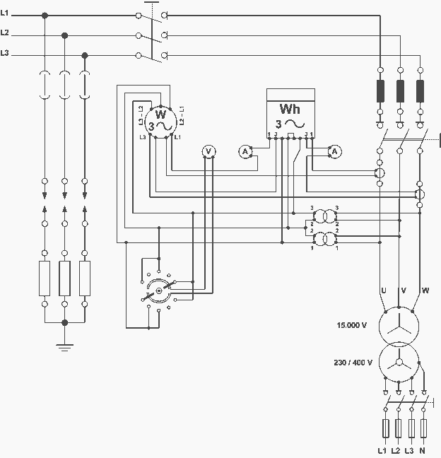
    3. Analytical (three-pole) schematic diagram

    Analytical (three-pole) schematic diagram of distributive power substation

    Analytical (three-pole) schematic diagram of distributive power substation

    High Voltage Substation At Rockville Indiana (VIDEO)

    Cant see this video? Click here to watch it on Youtube.

    References:

    - SIEMENS Substations Guide
    - Andreas Goutis, ‘Electrical drawing, Part 1’


    Manipulating Energized Conductors With Hot Stick

    $
    0
    0
    Manipulating Energized Conductors With Hot Stick

    Manipulating Energized Conductors With Hot Stick (photo by lineman.co.nz)

    Types of Hot Sticks

    Hot sticks are poles made of an insulating material.

    They have tools and/or fittings on the ends which allow workers to manipulate energized conductors and equipment from a safe distance.

    Hot sticks vary in length depending on the voltage level of the energized equipment and the work to be performed. Modern hot sticks are made of fiberglass and/or epoxiglass. Older designs were made of wood which was treated and painted with chemical-, moisture-, and temperature- resistant materials.

    Figure 1 is an example of a simple hot stick fitted with a tool suitable for operation of open-air disconnect switches.

    Typical hot stick

    Figure 1 - Typical hot stick


    Hot sticks can be fitted with a variety of tools and instruments.

    The most common fitting is the NEMA standard design shown in Fig. 2 as the standard universal fitting.

    Various fittings, couplings, and tools for hot sticks

    Figure 2 - Various fittings, couplings, and tools for hot sticks


    This fitting allows a variety of tools and equipment to be connected to the hot stick.

    Figure 2 also shows other attachments and extensions that can be used to increase the usefulness of hot sticks. In addition to the equipment, hot sticks can also be equipped with: wrenches, sockets, screwdrivers, cutters, saws and other such tools.

    Hot sticks can also be seen in telescoping (Figure 3) and so-called shotgun models (Figure 4).

    The telescoping type of hot stick is composed of several hollow, tubular sections which nest inside of each other.

    Telescoping hot stick

    Figure 3 - Telescoping hot stick


    Shotgun-type hot stick

    Figure 4 - Shotgun-type hot stick


    The topmost section is first extended and locked in place by means of a spring-loaded button which snaps into a hole. The user of the hot stick extends as many of the sections as are required to accomplish the job at hand.

    The telescoping hot stick makes very long hot stick lengths available which then collapse to a small, easy-tocarry assembly.

    The shotgun hot stick (Figure 4) has a sliding lever mechanism that allows the user to open and close a clamping hook mechanism at the end. In this way the user can attach the stick to a disconnect ring and then close it. After the switch is operated, the shotgun mechanism is operated to open the hook.

    The shotgun stick gets its name from its similarity to the pump-action shotgun.

    Typical hot stick kit for electricians and line workers

    Figure 5 - Typical hot stick kit for electricians and line workers


    Figure 5 shows a hot stick kit with several sections and various tools. This type of package provides a variety of configurations which will satisfy most of the day-to-day needs for the electrician and the overhead line worker.

    The kit includes the following components:

    1. Six 4-ft sections of an epoxiglas snap-together hot stick
    2. Aluminum disconnect head for opening and closing switches and enclosed cutouts
    3. Nonmetallic disconnect head for use in indoor substations where buswork and switches are in close proximity
    4. Clamp stick head for use with 6-in-long eye-screw ground clamps. This is used to apply and remove safety grounds
    5. Tree trimmer attachment with 1 ft of additional stick and pull rope used to close jaws of the trimmer
    6. Pruning saw
    7. Pistol-grip saw handle for use when tree limbs can be reached and insulation is not required
    8. Heavy-duty vinyl-impregnated storage case

    Electricians involved primarily in indoor work might wish to substitute other tools for the tree trimming and pruning attachments.


    When to Use Hot Stick?

    Hot stick should be used to insulate and isolate the electrician from the possibility of electric shock, arc, or blast.

    Typical procedures requiring use of hot sticks:

    Medium voltage and higher:
    • Voltage measurement
    • Any repairs or modifications to energized equipment

    All voltages:
    • Operation of disconnects and cutouts
    • Application of safety grounds


    How to Use It?

    The specifics of hot stick use will depend upon the task being performed and the location in which the worker is positioned. As a general rule, if hot sticks are being used, the worker should also wear other protective clothing.

    At a minimum, rubber gloves and face shields should be employed. However, many recommend that flash suits should also be worn, especially when safety grounds are being applied.

    Before each use the hot stick should be closely inspected for signs of physical damage which may affect its insulating ability. If the hot stick is cracked, split, or otherwise damaged, it should be taken out of service.

    Testing Requirements

    ASTM Standard F 711 requires that manufacturers test hot sticks to very stringent standards before they are sold. Additionally, OSHA standards require that hot sticks be inspected and/or tested periodically.

    The following should be the minimum:

    1. Hot sticks should be closely inspected for damage or defects
      a) Prior to each use
      b) At least every two years
    2. If any damage or defects are noted the hot stick should be repaired or replaced
    3. Hot sticks should be electrically tested according to ASTM Standard F 711
      a) Anytime an inspection reveals damage or a defect
      b) Every two years

    Using Hot-Stick (VIDEO)

    Cant see this video? Click here to watch it on Youtube.

    Resource: Electrical Safety Handbook – John Cadick, Mary Capelli-Schellpfeffer and Dennis K. Neitzel
    (Get this handbook from Amazon)

    What is transformer rating based on?

    $
    0
    0
    What is transformer rating based on?

    What is transformer rating based on? (on photo: Transformer produced by Japanese transformer manufacturer Kitashiba Electric Co., Ltd.)

    Temperature & Insulation

    In the U.S., transformers are rated based on the power output they are capable of delivering continuously at a specified rated voltage and frequency under “usual” operating conditions without exceeding prescribed internal temperature limitations.

    Insulation is known to deteriorate with increases in temperature, so the insulation chosen for use in transformers is based on how long it can be expected to last by limiting the operating temperature.

    The temperature that insulation is allowed to reach under operating conditions essentially determines the output rating of the transformer, called the kVA rating.

    Standardization has led to temperatures within a transformer being expressed in terms of the rise above ambient temperature, since the ambient temperature can vary under operating or test conditions.

    Transformers are designed to limit the temperature based on the desired load, including the average temperature rise of a winding, the hottest-spot temperature rise of a winding, and, in the case of liquid-filled units, the top liquid temperature rise. To obtain absolute temperatures from these values, simply add the ambient temperature.

    Standard temperature limits for liquid-immersed power transformers are listed in Table below.

    Standard limits for Temperature Rises Above Ambient

    Temperature riseTemperature
    Average winding temperature rise65°C **
    Hot spot temperature rise80°C
    Top liquid temperature rise65°C

    ** The base rating is frequently specified and tested as a 55°C rise.

    The normal life expectancy of a power transformer is generally assumed to be about 30 years of service when operated within its rating. However, under certain conditions, it may be overloaded and operated beyond its rating, with moderately predictable “loss of life.”

    Situations that might involve operation beyond rating include emergency rerouting of load or through-faults prior to clearing of the fault condition.

    Outside the U.S., the transformer rating may have a slightly different meaning. Based on some standards, the kVA rating can refer to the power that can be input to a transformer, the rated output being equal to the input minus the transformer losses.

    Power transformers have been loosely grouped into three market segments based on size ranges.

    These three segments are:

    1. Small power transformers: 500 to 7500 kVA
    2. Medium power transformers: 7500 to 100 MVA
    3. Large power transformers: 100 MVA and above

    Note that the upper range of small power and the lower range of medium power can vary between 2,500 and 10,000 kVA throughout the industry.

    It was noted that the transformer rating is based on “usual” service conditions, as prescribed by standards. Unusual service conditions may be identified by those specifying a transformer so that the desired performance will correspond to the actual operating conditions.

    Unusual service conditions include, but are not limited to, the following: high (above 40˚C) or low (below –20˚C) ambient temperatures, altitudes above 1000 m above sea level, seismic conditions, and loads with total harmonic distortion above 0.05 per unit.

    Reference: Electric Power Transformer Engieneering – Leo L. Grigsby
    (Get this book from Google Books)

    Types and Applications Of Overcurrent Relay (part 1)

    $
    0
    0
    Types, applications and connections of Overcurrent relay

    Types, applications and connections of Overcurrent relay (on photo: Transmission lines from Gillam to Churchill)

    Types of protection

    Protection schemes can be divided into two major groupings:

    1. Unit schemes
    2. Non-unit schemes

    1. Unit Type Protection

    Unit type schemes protect a specific area of the system, i.e., a transformer, transmission line, generator or bus bar.

    The unit protection schemes is based on Kirchhoff’s Current Law – the sum of the currents entering an area of the system must be zero.

    Any deviation from this must indicate an abnormal current path. In these schemes, the effects of any disturbance or operating condition outside the area of interest are totally ignored and the protection must be designed to be stable above the maximum possible fault current that could flow through the protected area.

    Go back to Index ↑


    2. Non unit type protection

    The non-unit schemes, while also intended to protect specific areas, have no fixed boundaries. As well as protecting their own designated areas, the protective zones can overlap into other areas. While this can be very beneficial for backup purposes, there can be a tendency for too great an area to be isolated if a fault is detected by different non unit schemes.

    The most simple of these schemes measures current and incorporates an inverse time characteristic into the protection operation to allow protection nearer to the fault to operate first.

    The non unit type protection system includes following schemes:
    1. Time graded overcurrent protection
    2. Current graded overcurrent protection
    3. Distance or Impedance Protection

    Go back to Index ↑

    2.1 Overcurrent protection

    This is the simplest of the ways to protect a line and therefore widely used.

    It owes its application from the fact that in the event of fault the current would increase to a value several times greater than maximum load current. It has a limitation that it can be applied only to simple and non costly equipments.

    Go back to Index ↑


    2.2 Earth fault protection

    The general practice is to employ a set of two or three overcurrent relays and a separate overcurrent relay for single line to ground fault. Separate earth fault relay provided makes earth fault protection faster and more sensitive.

    Earth fault current is always less than phase fault current in magnitude.

    Therefore, relay connected for earth fault protection is different from those for phase to phase fault protection.

    Go back to Index ↑


    Various types of Line Faults

    NoType of FaultOperation of  Relay
    1Phase to Ground fault (Earth Fault)Earth Fault Relay
    2Phase to Phase fault Not with GroundRelated Phase Overcurrent relays
    3Double phase to Ground faultRelated Phase Overcurrent relays and Earth Fault relays

    Go back to Index ↑


    Overcurrent Relay Purpose and Ratings

    A relay that operates or picks up when it’s current exceeds a predetermined value (setting value) is called Overcurrent Relay.

    Overcurrent protection protects electrical power systems against excessive currents which are caused by short circuits, ground faults, etc. Overcurrent relays can be used to protect practically any power system elements, i.e. transmission lines, transformers, generators, or motors.

    For feeder protection, there would be more than one overcurrent relay to protect different sections of the feeder. These overcurrent relays need to coordinate with each other such that the relay nearest fault operates first.

    Use time, current and a combination of both time and current are three ways to discriminate adjacent overcurrent relays.

    OverCurrent Relay gives protection against:

    Overcurrent includes short-circuit protection, and short circuits can be:

    1. Phase faults
    2. Earth faults
    3. Winding faults

    Short-circuit currents are generally several times (5 to 20) full load current. Hence fast fault clearance is always desirable on short circuits.

    Go back to Index ↑


    Primary requirement of Overcurrent protection

    The protection should not operate for starting currents, permissible overcurrent, current surges. To achieve this, the time delay is provided (in case of inverse relays).

    The protection should be co-ordinate with neighboring overcurrent protection.

    Overcurrent relay is a basic element of overcurrent protection.

    Go back to Index ↑


    Purpose of overcurrent Protection

    These are the most important purposes of overcurrent relay:

    • Detect abnormal conditions
    • Isolate faulty part of the system
    • Speed Fast operation to minimize damage and danger
    • Discrimination Isolate only the faulty section
    • Dependability / reliability
    • Security / stability
    • Cost of protection / against cost of potential hazards

    Go back to Index ↑


    Overcurrent Relay Ratings

    In order for an overcurrent protective device to operate properly, overcurrent protective device ratings must be properly selected. These ratings include voltage, ampere and interrupting rating.

    If the interrupting rating is not properly selected, a serious hazard for equipment and personnel will exist.

    Current limiting can be considered as another overcurrent protective device rating, although not all overcurrent protective devices are required to have this characteristic

    Voltage Rating: The voltage rating of the overcurrent protective device must be at least equal to or greater than the circuit voltage. The overcurrent protective device rating can be higher than the system voltage but never lower.

    Ampere Rating: The ampere rating of a overcurrent protecting device normally should not exceed the current carrying capacity of the conductors As a general rule, the ampere rating of a overcurrent protecting device is  selected at 125% of the continuous load current.

    Go back to Index ↑


    Difference between Overcurrent and Overload protection

    Overcurrent protection protects against excessive currents or currents beyond the acceptable current ratings, which are resulting from short circuits, ground faults and overload conditions.

    While, the overload protection protects against the situation where overload current causes overheating of the protected equipment.

    The overcurrent protection is a bigger concept So that the overload protection can be considered as a subset of overcurrent protection.

    The overcurrent relay can be used as overload (thermal) protection when protects the resistive loads, etc., however, for motor loads, the overcurrent relay cannot serve as overload protection Overload relays usually have a longer time setting than the overcurrent relays.

    Go back to Index ↑


    Types of Overcurrent Relay

    These are the types of overcurrent relay:

    1. Instantaneous Overcurrent (Define Current) Relay
    2. Define Time Overcurrent Relay
    3. Inverse Time Overcurrent Relay (IDMT Relay)
    • Moderately Inverse
    • Very Inverse Time
    • Extremely Inverse
  • Directional overcurrent Relay
  • Go back to Index ↑


    1. Instantaneous Overcurrent relay (Define Current)

    Definite current relay operate instantaneously when the current reaches a predetermined value.

    Instantaneous Overcurrent Relay - Definite Current

    Instantaneous Overcurrent Relay - Definite Current


    • Operates in a definite time when current exceeds its Pick-up value.
    • Its operation criterion is only current magnitude (without time delay).
    • Operating time is constant.
    • There is no intentional time delay.
    • Coordination of definite-current relays is based on the fact that the fault current varies with the position of the fault because of the difference in the impedance between the fault and the source
    • The relay located furthest from the source operate for a low current value
    • The operating currents are progressively increased for the other relays when moving towards the source.
    • It operates in 0.1s or less

    Application: This type is applied to the outgoing feeders.

    Go back to Index ↑


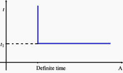
    2. Definite Time Overcurrent Relays

    In this type, two conditions must be satisfied for operation (tripping), current must exceed the setting value and the fault must be continuous at least a time equal to time setting of the relay.

    Definite time of overcurrent relay

    Definite time of overcurrent relay


    Modern relays may contain more than one stage of protection each stage includes each own current and time setting.

    1. For Operation of Definite Time Overcurrent Relay operating time is constant
    2. Its operation is independent of the magnitude of current above the pick-up value.
    3. It has pick-up and time dial settings, desired time delay can be set with the help of an intentional time delay mechanism.
    4. Easy to coordinate.
    5. Constant tripping time independent of in feed variation and fault location.

    Drawback of Relay:

    1. The continuity in the supply cannot be maintained at the load end in the event of fault.
    2. Time lag is provided which is not desirable in on short circuits.
    3. It is difficult to co-ordinate and requires changes with the addition of load.
    4. It is not suitable for long distance transmission lines where rapid fault clearance is necessary for stability.
    5. Relay have difficulties in distinguishing between Fault currents at one point or another when fault impedances between these points are small, thus poor discrimination.

    Application:

    Definite time overcurrent relay is used as:

    1. Back up protection of distance relay of transmission line with time delay.
    2. Back up protection to differential relay of power transformer with time delay.
    3. Main protection to outgoing feeders and bus couplers with adjustable time delay setting.

    Go back to Index ↑


    3. Inverse Time Overcurrent Relays (IDMT Relay)

    In this type of relays, operating time is inversely changed with current. So, high current will operate overcurrent relay faster than lower ones. There are standard inverse, very inverse and extremely inverse types.

    Discrimination by both ‘Time’ and ‘Current’. The relay operation time is inversely proportional to the fault current.

    Inverse Time relays are also referred to as Inverse Definite Minimum Time (IDMT) relay.
    Inverse Definite Minimum Time (IDMT)

    Inverse Definite Minimum Time (IDMT)


    The operating time of an overcurrent relay can be moved up (made slower) by adjusting the ‘time dial setting’. The lowest time dial setting (fastest operating time) is generally 0.5 and the slowest is 10.

    • Operates when current exceeds its pick-up value.
    • Operating time depends on the magnitude of current.
    • It gives inverse time current characteristics at lower values of fault current and definite time characteristics at higher values
    • An inverse characteristic is obtained if the value of plug setting multiplier is below 10, for values between 10 and 20 characteristics tend towards definite time characteristics.
    • Widely used for the protection of distribution lines.

    Based on the inverseness it has three different types:

    Inverse types

    Inverse types


    Go back to Index ↑

    3.1. Normal Inverse Time Overcurrent Relay

    The accuracy of the operating time may range from 5 to 7.5% of the nominal operating time as specified in the relevant norms. The uncertainty of the operating time and the necessary operating time may require a grading margin of 0.4 to 0.5 seconds.

    It’s used when Fault Current is dependent on generation of fault not fault location.

    Normal inverse time Overcurrent Relay is relatively small change in time per unit of change of current.

    Application:

    Most frequently used in utility and industrial circuits. especially applicable where the fault magnitude is mainly dependent on the system generating capacity at the time of fault.

    Go back to Index ↑


    3.2. Very Inverse Time Overcurrent Relay

    • Gives more inverse characteristics than that of IDMT.
    • Used where there is a reduction in fault current, as the distance from source increases.
    • Particularly effective with ground faults because of their steep characteristics.
    • Suitable if there is a substantial reduction of fault current as the fault distance from the power source increases.
    • Very inverse overcurrent relays are particularly suitable if the short-circuit current drops rapidly with the distance from the substation.
    • The grading margin may be reduced to a value in the range from 0.3 to 0.4 seconds when overcurrent relays with very inverse characteristics are used.
    • Used when Fault Current is dependent on fault location.
    • Used when Fault Current independent of normal changes in generating capacity.

    Go back to Index ↑


    3.3. Extremely Inverse Time Overcurrent Relay

    • It has more inverse characteristics than that of IDMT and very inverse overcurrent relay.
    • Suitable for the protection of machines against overheating.
    • The operating time of a time overcurrent relay with an extremely inverse time-current characteristic is approximately inversely proportional to the square of the current
    • The use of extremely inverse overcurrent relays makes it possible to use a short time delay in spite of high switching-in currents.
    • Used when Fault current is dependent on fault location
    • Used when Fault current independent of normal changes in generating capacity.

    Application:

    • Suitable for protection of distribution feeders with peak currents on switching in (refrigerators, pumps, water heaters and so on).
    • Particular suitable for grading and coordinates with fuses and re closes
    • For the protection of alternators, transformers. Expensive cables, etc.

    Go back to Index ↑


    3.4. Long Time Inverse Overcurrent Relay

    The main application of long time overcurrent relays is as backup earth fault protection.


    4. Directional Overcurrent Relays

    When the power system is not radial (source on one side of the line), an overcurrent relay may not be able to provide adequate protection. This type of relay operates in on direction of current flow and blocks in the opposite direction.

    Three conditions must be satisfied for its operation: current magnitude, time delay and directionality. The directionality of current flow can be identified using voltage as a reference of direction.

    Go back to Index ↑


    Application of Overcurrent Relay

    Motor Protection:

    • Used against overloads and short-circuits in stator windings of motor.
    • Inverse time and instantaneous overcurrent phase and ground
    • Overcurrent relays used for motors above 1000 kW.

    Transformer Protection:

    • Used only when the cost of overcurrent relays are not justified.
    • Extensively also at power-transformer locations for external-fault back-up protection.

    Line Protection:

    • On some sub transmission lines where the cost of distance relaying cannot be justified.
    • primary ground-fault protection on most transmission lines where distance relays are used for phase faults.
    • For ground back-up protection on most lines having pilot relaying for primary protection.

    Distribution Protection:

    Overcurrent relaying is very well suited to distribution system protection for the following reasons:

    • It is basically simple and inexpensive.
    • Very often the relays do not need to be directional and hence no PT supply is required.
    • It is possible to use a set of two O/C relays for protection against inter-phase faults and a separate Overcurrent relay for ground faults.

    Go back to Index ↑

    Connections Of Overcurrent Relay (part 2)

    $
    0
    0
    Connections Of Overcurrent Relay

    Connections Of Overcurrent Relay (part 2)


    Continued from first part: Types and Applications Of Overcurrent Relay (part 1)


    Connections of Overcurrent and Earth Fault Relays

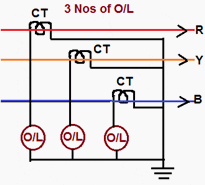
    1. 3 Nos O/C relay for overcurrent and earth fault protection

    It’s used for:

    • 3-phase faults the overcurrent relays in all the 3-phases act.
    • Phase to phase faults the relays in only the affected phases operate.
    • Single line to ground faults only the relay in the faulty phase gets the fault current and operates.

    Even then with 3 overcurrent relays, the sensitivity desired and obtainable with earth leakage overcurrent relays cannot be obtained in as much as the high current setting will have to be necessarily adopted for the overcurrent relay to avoid operation under maximum load condition.

    3 Nos O/C Relay for Over Current and Earth Fault Protection

    3 Nos O/C Relay for Over Current and Earth Fault Protection


    Over current relays generally have 50% to 200% current setting while earth leakages over current relays have either 10% to 40% or 20% to 80% current settings.

    One important thing to be noted here is that the connection of the star points of both the C.T. secondary’s and relay windings by a neutral conductor should be made.

    A scheme without the neutral conductor will be unable to ensure reliable relay operation in the event of single phase to earth faults because the secondary current in this case (without star-point interconnection) completes its circuit through relay and C.T. windings which present large impedance.

    This may lead to failure of protection and sharp decrease in reduction of secondary currents by CTs.

    It is not sufficient if the neutral of the CTs and neutral of the relays are separately earthed. A conductor should be run as stated earlier.


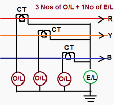
    2.  3 No O/C Relay+ 1 No E/F Relay for Overcurrent and Earth Fault Protection

    The scheme of connection for 3 Nos Over current Relay 1 No Earth Fault Relay is shown in figure below.

    3 No O/C Relay+ 1 No E/F Relay for Overcurrent and Earth Fault Protection

    3 No O/C Relay+ 1 No E/F Relay for Overcurrent and Earth Fault Protection


    Under normal operating conditions the three phase fault conditions and current in the 3-phase are equal and symmetrically displaced by 12 Deg. Hence the sum of these three currents is zero. No current flow through the earth fault relay.

    In case of phase to phase faults (say a short between R and Y phases) the current flows from R-phase up to the point of fault and return back through ‘Y’ phase. Thus only O/L relays in R and Y phases get the fault and operate.

    Only earth faults cause currents to flow through E/L relay. A note of caution is necessary here. Only either C.T secondary star point of relay winding star point should be earthed.

    Earthing of both will short circuit the E/L relay and make it inoperative for faults.


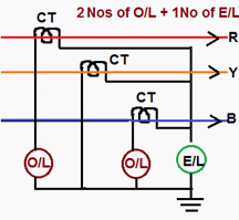
    3.  2 No O/C Relay + 1 No E/F Relay for Over Current and Earth Fault Protection

    The two over current relays in R and B phases will respond to phase faults. At least one relay will operate for fault involving two phase.

    2 No O/C Relay + 1 No E/F Relay for Over Current and Earth Fault Protection

    2 No O/C Relay + 1 No E/F Relay for Over Current and Earth Fault Protection


    For fault involving ground reliance is placed on earth fault relay.

    This is an economical version of 3-O/L and 1-E/L type of protection as one overcurrent relay is saved. With the protection scheme as shown in Figure complete protection against phase and ground fault is afforded.


    Current Transformer Secondary Connections

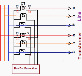
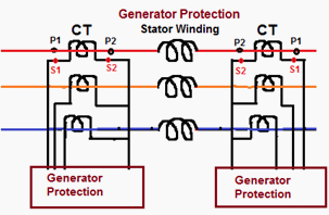
    For protection of various equipment of Extra High Voltage class, the star point on secondary’s of CT should be made as follows for ensuring correct directional sensitivity of the protection scheme.

    Transmission Line , Bus Bar and Transformer:

    • For Transmission Lines – Line side
    • For Transformers – Transformer side
    • For Bus bar – Bus side
    Transmission Line , Bus Bar & Transformer scheme

    Transmission Line , Bus Bar & Transformer scheme

    Generator Protection:

    • Generator Protection – Generator Side
    Generator protection scheme

    Generator protection scheme


    The above method has to be followed irrespective of polarity of CT’s on primary side.

    For example, in line protection, if ‘P1’ is towards bus then ‘S2’s are to be shorted and if ‘P2’ is towards bus then ‘S1’s are to be shorted.

    Standard Overcurrent and Earth Fault Protection

    NoName of the EquipmentProtection
    111 KV FeedersA) 2 No Over Current and one no Earth Fault IDMT relays
    B) 2 No Instantaneous Overcurrent (highest) and one no Instantaneous Earth fault relay
    28 MVA Capacity OR Two Transformer in a Substation (Irrespective of capacity)HV side: 33 KV Breaker (Individual or Group Control with 3 Over Current and One Earth Fault IDMT relays
    LV Side: Individual 11 KV Breakers with 3 Over Current and One Earth Fault IDMT relays
    38 MVA Power TransformerDifferential relays OR REF relays on LV side
    4Only one PTR in a Sub Station (Less than 8 MVA)HV Side: HG fuse
    LV Side: 11 KV Breaker with 3 Over Current and one E/F IDMT relay

    How to Monitor Wind Speed?

    $
    0
    0
    How to monitor wind speed?

    How to monitor wind speed? (Photo by: Andy @ Flickr)

    Wind Speed – Mistery Or Not?

    When considering wind power, most people ask what the average annual wind speed is and how to get that number. The usual response is that you must monitor the wind speed at your site for at least 12 months, preferably longer, to determine whether a wind generator will work for you.

    Sounds too long? Well, yes and no…

    For a home system, this isn’t necessary. The costs involved in collecting wind data may not be justified when compared to the total cost of a small wind machine.

    There is no economic formula to determine this, but it doesn’t make much sense to spend $1,200 on instrumentation if your wind machine costs only $3,000. You can get close to the actual number by making an educated guess using the empirical methods.

    Options For Monitoring The Wind Speed

    If you decide to monitor wind speeds, you have several options.

    1 The first is to buy a weather anemometer and record observations on a regular basis. This is the least expensive way to collect wind data, but it has disadvantages. For the data to be valid, you must be methodical in collecting it.

    Weather anemometer

    Weather anemometer


    Recording one instantaneous wind speed per day won’t do.

    If you can’t record multiple wind speeds throughout a day, the quality of your data is questionable.

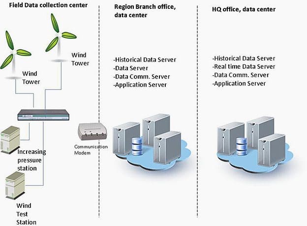
    2 A second option is to automate data collection by installing a data collection board in a personal computer. This method works, but the computer must stay on all the time, and there are additional costs.

    Since these are not plug-and-play components, some computer hardware and software knowledge is necessary.

    The wind power monitoring system architecture

    The wind power monitoring system architecture

    3 A third option is to invest in an anemometer system specifically designed for collecting wind data. The least expensive systems simply average the wind speed over time and cost $200 to $300. These systems usually are sold without towers.

    While the average wind speed is a useful measurement, it also is important to know the wind speed distribution.

    More sophisticated systems usually consist of:
    1. A portable tower,
    2. Instrumentation and
    3. Data logger.

    These systems are reliable and accurate, but they are expensive.

    After collecting data, you have equipment that may or may not be useful to you. The secondary market for used towers and data loggers is limited.

    If you buy a used system, consider new instrumentation. This will help ensure quality data.

    Usually the system has an anemometer and a wind vane. The anemometer measures wind velocity, while the wind vane registers direction. Both instruments should be mounted on a wind pole or tower that is as close as possible to the height at which your wind machine will be mounted.

    If your anemometer is mounted too low, it will underestimate the actual wind resource available.

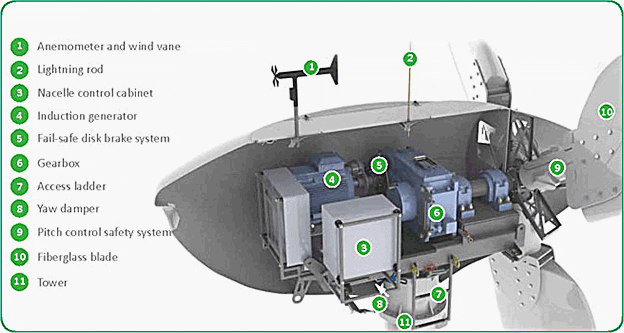
    Endurance E-3120 50kW Wind Turbine Specification

    Endurance E-3120 50kW Wind Turbine Specification


    It is generally recommended that the hub height for small machines between 60 feet and 120 feet. Your anemometer also should be within this range.

    To generate data for all seasons, average wind speeds along with distribution and peak gust information should be recorded for a minimum of three months, but ideally for a full year. Wind speed data can then be used with performance data for various wind machines to determine the expected output for each machine at your site.

    If you collect data for a short time, it can be correlated with existing data to produce a model of the wind speeds at the potential site. To do this, you need to develop a “correction factor”.

    For example, assume you have collected average wind speeds of 12.8 mph, 10.8 mph and 10.4 mph for the last three months, and the published data from a nearby site for the same three months is 10.9, 10.2 and 9.5.

    Dividing your data by the published data will give you the following deviation factors: 1.174, 1.059 and 1.095. Averaging these results in a correction factor of 1.109. You can multiply the remaining published data by this correction factor to estimate wind speeds at your site. This method involves a fair amount of interpretation, and some sites do not correlate well.

    If you are considering a large project, on-site data is a necessity.

    These systems require taller towers – 40 or 50 meters. They include multiple levels of instrumentation and data loggers that can be accessed remotely. Assessing a site’s potential for utilityscale wind development is an expensive undertaking that requires committing significant financial resources.


    Wind Turbines – How does it actually work? Investment?

    Cant see this video? Click here to watch it on Youtube.

    America used 3,200 billion kilowatt-hours of electricity in 1998.

    The Energy Information Agency predicts that consumption will increase to 4,400 billion kilowatt-hours in 2020. No single energy source can deliver all the electricity we need to fuel our economy.

    What do you think about this?

    Resource: Montana Wind Power – A Consumer’s Guide to Harnessing the Wind

    Did Tesla Discover the Secrets of Antigravity?

    $
    0
    0
    Did Tesla Discover the Secrets of Antigravity?

    The first of four candid photos taken of Tesla at a press conference at the Hotel New Yorker July 10, 1935, his seventy-ninth birthday.


    Nikola Tesla has been credited for the creation of much of the technology that we take for granted today.

    Without the genius of Tesla we would not have:

    • Radio,
    • Television,
    • AC electricity,
    • Tesla coil,
    • Flourescent lighting,
    • Neon lighting,
    • Radio control devices,
    • Robotics,
    • X-rays,
    • Radar,
    • Microwaves and
    • Dozens of other amazing inventions.

    Quite an impressive list you must say.

    Because of this, it is no surprise that Tesla also delved into the world of flight and possibly, antigravity. In fact, his last patent in 1928 (#6,555,114), was for a flying machine that resembled both a helicopter and an airplane.

    Before he died, Tesla reportedly devised plans for the engine of a spaceship. He called it the anti-electromagnetic field drive or Space Drive.

    William R. Lyne writes in Occult Ether Physics (Creatopia Productions), that a lecture Tesla prepared for the Institute of Immigrant Welfare (May. 12, 1938), dealt with his Dynamic Theory of Gravity. Tesla said in his lecture that this was: “One of two far reaching discoveries, which I worked out in all details in the years 1893 and 1894.”

    While researching Tesla’s statements, Lyne discovered that more complete statements concerning these discoveries could only be gleaned from scattered and sparse sources, because Tesla’s papers are concealed in government vaults for national security reasons. When Lyne specifically asked for these papers at the National Security Research Center (now the Robert J. Oppenheimer Research Center) in 1979, he was denied access because they were still classified.

    In his 1938 lecture, Tesla said he was progressing with the work, and hoped to give the theory to the world very soon.


    Discoveries

    The two great discoveries to which Tesla referred, were:

    1. The Dynamic Theory of Gravity

    Which assumed a field of force which accounts for the motions of bodies in space.

    Assumption of this field of force dispenses with the concept of space curvature (ala Einstein); the ether has an indispensable function in the phenomena (of universal gravity, inertia, momentum, and movement of heavenly bodies, as well as all atomic and molecular matter).


    2. Environmental Energy

    The Discovery of a new physical Truth: there is no energy in matter other than that received from the environment. (Which goes against Einstein’s E=mc2).

    The usual Tesla birthday announcement – on his 79th birthday (1935) – Tesla made a brief reference to the theory saying it applies to molecules and atoms as well as to the largest heavenly bodies, and to “… all matter in the universe in any phase of its existence from its very formation to its ultimate disintegration“.

    In an article, Man’s Greatest Achievement, Tesla outlined his Dynamic Theory of Gravity by saying that the luminiferous ether fills all space. The ether is acted upon by the life-giving creative force and is thrown into “infinitesimal whirls” (“micro helices“) at near the speed of light, becoming ponderable matter. When the force subsides and motion ceases, matter reverts to the ether (a form of “atomic decay”).

    Man can harness these processes to: Precipitate matter from the ether. Create whatever he wants with the matter and energy derived. Alter the earth’s size. Control earth’s seasons (weather control). Guide earth’s path through the Universe, like a spaceship. Cause the collisions of planets to produce new suns and stars, heat, and light. Originate and develop life in infinite forms.

    When Tesla was 82, instead of speaking at a dinner party, he issued a written statement. Although this was soon after he had been struck by a car, his mind was obviously still capable of mounting an attack on Einstein’s theory of relativity:

    “I have worked out a dynamic theory of gravity in all details and hope to give this to the world very soon.”

    It explains the causes of this force and the motions of heavenly bodies under its influence so satisfactorily that it will put an end to idle speculations and false conceptions, as that of curved space.

    According to the relativists, space has a tendency to curvature owing to an inherent property or presence of celestial bodies. ”Granting a semblance of reality to this fantastic idea, it is still very self-contradictory. Every action is accompanied by an equivalent reaction and the effects of the latter are directly opposite to those of the former. Supposing that the bodies act upon the surrounding space causing curvature of the same, it appears to my simple mind that the curved spaces must react on the bodies and, producing the opposite effects, straighten out the curves.

    “Since action and reaction are coexistent, it follows that the supposed curvature of space is entirely impossible – However, even if it existed it would not explain the motions of the bodies as observed. Only the existence of a field of force can account for them and its assumption dispenses with space curvature. All literature on this subject is futile and destined to oblivion.”

    It is a great pity that Tesla never published his dynamic theory of gravity.

    Modern thinking about gravity suggests that when a heavy object moves it emits gravitational waves that radiate at the speed of light. These gravity waves behave in similar ways to many other types of waves. Tesla’s greatest inventions were all based on the study of waves. He always considered sound, light, heat, X-rays and radio waves to be related phenomena that could be studied using the same sort of maths.

    His differences with Einstein suggest that he had extended this thinking to gravity.

    In the 1980s he was proved to be right. A study of energy loss in a double neutron star pulsar called PSR 1913 + 16 proved that gravity waves exist. Tesla’s idea that gravity is a field effect is now taken more seriously than Einstein took it.

    Unfortunately, Tesla never revealed what had led him to this conclusion.

    He never explained his theory of gravitation to the world. The attack he made on Einstein’s work was considered outrageous by the scientific establishment of the time, and only now do we have enough understanding of gravity to realize that he was right.

    Resource: The Lost Journals of Nikola Tesla (Get it from Amazon)

    How Motor Really Works?

    $
    0
    0
    Motor action

    Figure 1 - A motor action


    The basic working of a motor is based on the fact that when ‘a current carrying conductor is placed in a magnetic field, it experiences a force’.

    If you take a simple DC motor, it has a current-carrying coil supported in between two permanent magnets (opposite pole facing) so that the coil can rotate freely inside. When the coil ends are connected to a DC source then the current will flow through it and it behaves like a bar magnet, as shown in Figure 1.

    As the current starts flowing, the magnetic flux lines of the coil will interact with the flux lines of the permanent magnet.

    This will cause a movement of the coil (Figures 1a, 1b, 1c, 1d) due to the force of attraction and repulsion between two fields. The coil will rotate until it achieves the 180° position, because now the opposite poles will be in front of each other (Figure 1e) and the force of attraction or repulsion will not exist.

    The role of the commutator: The commutator brushes just reverse the polarity of DC supply connected to the coil. This will cause a change in the direction of the current of the magnetic field and start rotating the coil by another 180° (Figure 1f).

    The brushes will move on like this to achieve continuous coil rotation of the motor.

    Similarly, the AC motor also functions on the above principle; except here, the commutator contacts remain stationary, because AC current direction continually changes during each half-cycle (every 180°).

    Resource: Practical Troubleshooting of Electrical Equipment and Control Circuits – M. Brown
    (Get it from Amazon)


    How Do We Define Hazardous Areas?

    $
    0
    0
    How Do We Define Hazardous Areas?

    How Do We Define Hazardous Areas? (On photo: Flammable liquid warning)

    What is the hazardous area?

    The first requirement is to know what a hazardous area is. The principal factors relevant to the classifications of a hazardous area are the nature of the gases or dust present in the potentially explosive atmosphere and the likelihood of that atmosphere being present.

    The concept of ‘zone classification’ has been developed to summarize these factors. The nature of the atmosphere is characterized by the chemical composition of the gas or dust and its auto-ignition temperature.

    The notions of ‘gas grouping’ and ‘temperature classification’ have been developed to formalize this.

    Before looking in more detail at these definitions, it is instructive to consider how explosions occur.

    A useful concept is that of the ‘hazard triangle’, Figure 1.

    The Hazard Triangle

    The Hazard Triangle


    The three sides of the triangle represent fuel, oxygen and a source of ignition, all of which are required to create an explosion. The fuel considered here is a flammable gas, vapour or liquid although dust may also be a potential fuel.

    Oxygen is present in air at a concentration of approximately 21%. The ignition source could be a spark or a high temperature.

    If the potentially flammable atmosphere is between the upper and lower flammable limits for the particular material and an ignition source is introduced then it will explode or burn. Obviously if any side of the hazardous triangle can be removed then a fire or explosion hazard cannot exist.

    Given that a hazardous area may contain fuel and oxygen, the basis for preventing explosion is ensuring that any ignition source is either eliminated or else does not come into contact with the fuel-oxygen mixture.

    If there is any possibility of oxygen enrichment, i.e. above 20% by volume, then special consideration is necessary to ensure safety.


    Zone classification

    Table 1 shows the IEC 79-10 zone classification used in Europe and most other parts of the world. The British Standard BS 5345 Part 2 will become obsolete and replaced by BS/EN/IEC 60079-10.

    IEC 79 classification of hazardous area zones

    Table 1 - IEC 79 classification of hazardous area zones

    The table also indicates which types of explosion protection are suitable for use within each zone. These explosion protection concepts are described later in the chapter.

    The American system of hazardous area classification is structured in a different way, according to the National Electrical Code – NEC.

    In brief, hazardous locations are classified as either Class 1 ‘Division 1’, where ignitable concentrations of flammable gases or vapours may be present during normal operation, or ‘Division 2’, where flammable gases or vapours occur in ignitable concentrations only in the event of an accident or a failure of a ventilation system.

    Class II and Class III Divisions 1 and 2 relate to combustible dust and fibres. The 1999 edition of the National Electric Code (NEC) introduced for the first time in the USA the zone classification concept as an alternative to the class and division definitions of hazardous locations, e.g. Class 1 Zones 0, 1 and 2 for gases and vapour.

    In the UK, the Factories Act states that where there is a risk of a flammable dust cloud, explosion protection and measures to reduce the risk of ignition will be required.

    The ATEX Directive legally requires dust hazards to be considered and classified as either Zone 20, 21 or 22.


    Gas grouping and temperature classification

    Different gases require different amounts of energy (by hot surface or spark) to ignite them and the two concepts of gas grouping and temperature classification are used in Europe to classify electrical apparatus according to its suitability for use with explosive atmospheres of particular gases.

    Table 2 lists common industrial gases in their appropriate gas groups:

    Gas group I is reserved for equipment suitable for use in coal mines.

    Gas group II which contains gases found in other industrial applications – is subdivided IIA, IIB, or IIC according to the relative flammability of the most explosive mixture of the gas with air.

    CENELEC/IEC gas grouping

    Table 2 - CENELEC/IEC gas grouping

    Table 3 defines each temperature class according to the maximum allowed apparatus surface temperature exposed to the surrounding atmosphere, and indicates common gases for which these classifications are appropriate.

    CENELEC/IEC temperature classification

    Table 3 - CENELEC/IEC temperature classification


    North American practice defines hazardous materials in classes. Flammable gases and vapours are Class 1 materials, combustible dusts are Class 2 materials and ‘flyings’ (such as sawdust) are Class 3 materials.

    Class 1 is subdivided into four groups depending on flammability:

    • A (e.g. acetylene),
    • B (e.g. hydrogen),
    • C (e.g. ethylene) and
    • D (e.g. propane, methane)

    Note that when compared with the IEC gas groupings, the subgroup letters are in opposite order of flammability.

    North American temperature classification is similar to IEC standards, but further subdivides the classes to give more specific temperature data.

    Resource: Newnes Electrical Pocket Book (Get it from Amazon)

    Medium Voltage Switchgear (1) – Basics of Switching Devices

    $
    0
    0
    Medium Voltage Switchgear (1) – Basics of Switching Devices

    Medium Voltage Switchgear (1) – Basics of Switching Devices

    Introduction to Medium Voltage

    According to international rules, there are only two voltage levels:

    1. Low voltage: up to and including 1kV AC (or 1,500V DC).
    2. High voltage: above 1kV AC (or 1,500V DC).

    Most electrical appliances used in household, commercial and industrial applications work with low voltage. High voltage is used not only to transmit electrical energy over very large distances, but also for regional distribution to the load centers via fine branches.

    However, because different high voltage levels are used for transmission and regional distribution, and because the tasks and requirements of the switchgear and substations are also very different, the term ‘medium voltage’ has come to be used for the voltages required for regional power distribution that are part of the high voltage range from 1kV AC up to and including 52kV AC.

    Most operating voltages in medium voltage systems are in the 3kV AC to 40.5kV AC range.

    The electrical transmission and distribution systems not only connect power stations and electricity consumers, but also, with their ‘meshed systems’, form a supraregional backbone with reserves for reliable supply and for the compensation of load differences.

    High operating voltages (and therefore low currents) are preferred for power transmission in order to minimize losses. The voltage is not transformed to the usual values of the low voltage system until it reaches the load centers close to the consumer.

    In public power supplies, the majority of medium voltage systems are operated in the 10kV to 30kV range (operating voltage). The values vary greatly from country to country, depending on the historical development of technology and the local conditions.


    1. Medium voltage equipment

    Apart from the public supply, there are still other voltages fulfilling the needs of consumers in industrial plants with medium voltage systems; in most cases, the operating voltages of the motors installed are decisive.

    Operating voltages between 3kV and 15kV are frequently found in industrial supply systems.

    In power supply and distribution systems, medium voltage equipment is available in:

    1. Power stations, for generators and station supply systems.
    2. Transformer substations of the primary distribution level (public supply system or systems of large industrial companies), in which power supplied from the high voltage system is transformed to medium voltage.
    3. Local supply, transformer or customer transfer substations for large consumers (secondary distribution level), in which the power is transformed from medium to low voltage and distributed to the consumer.
    Power distribution network scheme

    Power distribution network scheme

    2. Basics of Switching Devices

    Switching devices are devices used to close (make) or open (break) electrical circuits.

    The following stress can occur during making and breaking:

    • No-load switching
    • Breaking of operating currents
    • Breaking of short circuit currents

    What can the different switching devices do?

    Circuit breakers:

    Make and break all currents within the scope of their ratings, from small inductive and capacitive load currents up to the full short circuit current, and this under all fault conditions in the power supply system, such as earth faults, phase opposition, and so on.

    Switches:

    Switch currents up to their rated normal current and make on existing short circuits (up to their rated short circuit making current).

    Disconnectors (isolators):

    Used for no-load closing and opening operation. Their function is to isolate ‘downstream’ devices so they can be worked on.

    Three-position disconnectors:

    Combine the functions of disconnecting and earthing in one device. Three-position disconnectors are typical for GIS – Gas insulated switchgear.

    Switch disconnectors (load break switches):

    The combination of a switch and a disconnector, or a switch with isolating distance.

    Contactors:

    Load breaking devices with a limited short circuit making or breaking capacity. They are used for high switching rates.

    Earthing switches:

    To earth isolated circuits.

    Make-proof earthing switches (earthing switches with making capacity):

    Are used for the safe earthing of circuits, even if voltage is present, that is, also in the event that the circuit to be earthed was accidentally not isolated.

    Fuses:

    Consist of a fuse base and a fuse link. With the fuse base, an isolating distance can be established when the fuse link is pulled out in de-energized condition (like in a disconnector). The fuse link is used for one single breaking of a short circuit current.

    Surge arresters:

    To discharge loads caused by lightning strikes (external overvoltages) or switching operations and earth faults (internal overvoltages). They protect the connected equipment against impermissibly high voltages.

    Will be continued very soon…

    Medium Voltage Switchgear (2) – Selection of Switching Devices

    $
    0
    0
    Medium Voltage Switchgear (2) – Selection of Switching Devices

    Medium Voltage Switchgear (2) – Selection of Switching Devices


    Continued from first part: Medium Voltage Switchgear (1) – Basics of Switching Devices


    3. Selection of Switching Devices

    Switching devices are selected both according to their ratings and according to the switching duties to be performed, which also includes the switching rates.

    1. Selection according to ratings
    2. Selection according to endurance and switching rates
      1. Switches (general, sf6, air-break, vacuum)
      2. Circuit Breakers
      3. Disconnectors
      4. Earthing Switches
      5. Contactors

    3.1 Selection according to ratings

    The system conditions, that is, the properties of the primary circuit, determine the required parameters.

    The most important of these are:

    Rated voltage

    The upper limit of the system voltage the device is designed for. Because all high voltage switching devices are zero-current interrupters, except for some for fuses the system voltage is the most important dimensioning criterion.

    It determines the dielectric stress of the switching device by means of the transient recovery voltage and the recovery voltage, especially while switching off.

    Rated insulation level

    The dielectric strength from phase to earth, between phases and across the open contact gap, or across the isolating distance. The dielectric strength is the capability of an electrical component to withstand all voltages with a specific time sequence up to the magnitude of the corresponding withstand voltages.

    These can be operating voltages or higher frequency voltages caused by switching operations, earth faults (internal overvoltages) or lightning strikes (external overvoltages). The dielectric strength is verified by a lightning impulse withstand voltage test with the standard impulse wave of 1.2/50μs and a power frequency withstand voltage test (50Hz/1min).

    Rated normal current

    The current that the main circuit of a device can continuously carry under defined conditions. The temperature increase of components – especially contacts must not exceed defined values.

    Permissible temperature increases always refer to the ambient air temperature. If a device is mounted in an enclosure, it may be advisable to load it below its full rated current, depending on the quality of heat dissipation.

    Rated peak withstand current

    The peak value of the major loop of the short circuit current during a compensation process after the beginning of the current flow, which the device can carry in closed state.

    It is a measure for the electrodynamic (mechanical) load of an electrical component. For devices with full making capacity, this value is not relevant.

    Rated short circuit making current

    The peak value of the making current in case of short circuit at the terminals of the switching device. This stress is greater than that of the rated peak withstand current, because dynamic forces may work against the contact movement.

    Rated breaking current

    The load breaking current in normal operation. For devices with full breaking capacity and without a critical current range, this value is not relevant.

    Rated short circuit breaking current

    The root – mean – square value of the breaking current in case of short circuit at the terminals of the switching device.


    3.2 Selection according to endurance and switching rates

    If several devices satisfy the electrical requirements and no additional criteria have to be taken into account, the required switching rate can be used as an additional selection criterion.

    Table 1 through table 5 show the endurance of the switching devices, providing a recommendation for their appropriate use. The respective device standards distinguish between classes of mechanical (M) and electrical (E) endurance, whereby they can also be used together on the same switching device.

    Go to Content ↑


    Switches:

    Standard IEC 62271 – 103/VDE 0671 – 103 only specifies classes for the so called general-purpose switches. There are also ‘special switches’ and ‘switches for limited applications’.

    Important note:
    Disconnectors up to 52kV may only switch negligible currents up to 500mA (e.g., voltage transformer), or larger currents only when there is an insignificant voltage difference (e.g., during busbar transfer when the bus coupler is closed).

    General–purpose switches

    General-purpose switches must be able to break different types of operating currents (load currents, ring currents, currents of unloaded transformers, charging currents of unloaded cables and overhead lines), as well as to make on short circuit currents.

    General-purpose switches that are intended for use in systems with isolated neutral or with earth fault compensation must also be able to switch under earth fault conditions.


    SF6 (Sulfur hexafluoride) switches

    SF6 switches are appropriate when the switching rate is not more than once a month. These switches are usually classified as E3 with regard to their electrical endurance.


    Air-break or hard-gas switches

    Air-break or hard-gas switches are appropriate when the switching rate is not more than once a year. These switches are simpler and usually belong to the E1 class. There are also E2 versions available.


    Vacuum switches

    The switching capacity of vacuum switches is significantly higher than that of the M2/E2 classes. Vacuum switches are used for special tasks: mostly in industrial power supply systems, or when the switching rate is at least once a week.

    Table 1 - Classes for switches

    Table 1 - Classes for switches


    Go to Content ↑

    Circuit breakers

    VD4 medium voltage circuit breaker - ABB

    VD4 medium voltage circuit breaker - ABB


    Whereas the number of mechanical operating cycles is specifically stated in the M classes, the circuit breaker standard IEC 62271-100/VDE 0671-100 does not define the electrical endurance of the E classes by specific numbers of operating cycles; the standard remains very vague on this.

    The test duties of the short circuit type tests provide an orientation as to what is meant by ‘normal electrical endurance’ and ‘extended electrical endurance’. The number of make and break operations (Close, Open) is specified in Table 2.

    Modern vacuum circuit breakers can generally make and break the rated normal current up to the number of mechanical operating cycles.

    The switching rate is not a determining selection criterion, because circuit breakers are always used where short – circuit breaking capacity is required to protect equipment.

    Table 2 - Classes for circuit breakers

    Table 2 - Classes for circuit breakers


    Go to Content ↑

    Disconnectors

    Disconnectors do not have any switching capacity (switches for limited applications must only control some of the switching duties of a general-purpose switch). Switches for special applications are provided for switching duties such as switching of single capacitor banks, switching of ring circuits formed by transformers connected in parallel, or switching of motors in normal and locked condition.

    Therefore, classes are only specified for the number of mechanical operating cycles.

    Table 3 - Endurance classes for disconnectors

    Table 3 - Endurance classes for disconnectors


    Go to Content ↑

    Earthing switches

    With earthing switches, the E classes designate the short circuit making capacity (earthing on applied voltage). E0 corresponds to a normal earthing switch; switches of the E1 and E2 classes are also called make-proof or high-speed earthing switches.

    The standard does not specify how often an earthing switch can be actuated purely mechanically; there are no M classes for these switches.

    Table 4 - Endurance classes for earthing switches

    Table 4 - Endurance classes for earthing switches


    Go to Content ↑

    Contactors

    Toshiba vacuum contactors, 400A

    Toshiba vacuum contactors, 400A. Current limiting, high interrupting power fuses.


    The standard has not specified any endurance classes for conductors yet. Commonly used conductors today have a mechanical and electrical endurance in the range of 250,000 to 1,000,000 operating cycles.

    They are used wherever switching operations are performed very frequently, e.g., more than once per hour.

    Table 5 - Classes for contactors

    Table 5 - Classes for contactors


    References:

    - SIEMENS Power Engineering Guide, ‘Switchgear and Substations’

    Go to Content ↑

    Using High-Speed Grounding Switches

    $
    0
    0
    Using High-Speed Grounding Switches

    Using High-Speed Grounding Switches


    Automatic high-speed grounding switches are applied for protection of power transformers when the cost of supplying other protective equipment is deemed unjustifiable and the amount of system disturbance that the high-speed grounding switch creates is judged acceptable.

    The switches are generally actuated by discharging a spring mechanism to provide the ‘‘high-speed’’ operation.

    The grounding switch operates to provide a deliberate ground fault on one phase of the high-voltage bus supplying the power transformer, disrupting the normally balanced 120° phase shifted three-phase system by effectively removing one phase and causing the other two phases to become 180º phase shifted relative to each other.

    This system imbalance is remotely detected by protective relaying equipment that operates the transmission line breakers at the remote end of the line supplying the power transformer, tripping the circuit open to clear the fault. This scheme also imposes a voltage interruption to all other loads connected between the remote circuit breakers and the power transformer as well as a transient spike to the protected power transformer, effectively shortening the transformer’s useful life.

    Frequently, a system utilizing a high-speed ground switch also includes the use of a motor operated disconnect switch and a relay system to sense bus voltage.

    The relay system’s logic allows operation of the motor operated disconnect switch when there is no voltage on the transmission line to provide automatic isolation of the faulted power transformer and to allow reclosing operations of the remote breakers to restore service to the transmission line and to all other loads fed by this line.

    The grounding switch scheme is dependent on the ability of the source transmission line relay protection scheme to recognize and clear the fault by opening the remote circuit breaker. Clearing times are necessarily longer since the fault levels are not normally within the levels appropriate for an instantaneous trip response.

    The lengthening of the trip time also imposes additional stress on the equipment being protected and should be considered when selecting this method for power transformer protection.

    High-speed grounding switches are usually considered when relative fault levels are low so that the risk of significant damage to the power transformer due to the extended trip times is mitigated.

    Resource: Electric Power Substations Engineering – J. D. McDonald (Get it from Amazon)

    Direct Starting Of Squirrel-Cage Induction Motors

    $
    0
    0
    Direct Starting Of Squirrel-Cage Induction Motors

    Direct Starting Of Squirrel-Cage Induction Motors

    Introduction

    The direct starting (Direct On Line, DOL) is the simplest and most cost-efficient method of starting a motor.

    This is assuming that the power supply can easily deliver the high starting current and that the power transmission components and the working machine are suitable for the high starting torques.

    Example of a two-component starter for direct starting consisting of a motor protection circuit breaker and a contactor

    Figure 1 - Example of a two-component starter for direct starting consisting of a motor protection circuit breaker and a contactor


    With direct starting, the poles of contactor and motor protective device are connected to the pole conductors (Figure 1) and the operating current of the motor flows through them.

    The motor protective device must therefore be adjusted to the rated operational current of the motor.

    The contactor is selected according to the rated operational current Ie and the respective utilization category:
    • AC-3 Squirrel-cage induction motors: Starting, switching off during running
    • AC-4 Squirrel-cage induction motors: Starting, plugging, inching

    For AC-3 operation, allowance must always be made in practice for sporadic inching operations, for example during commissioning, in case of faults or in service work.

    Contactors from Rockwell Automation comply with these requirements and may be rated without risk according to AC-3 values; for the large majority of devices, the rated operational currents for the utilization categories AC-3 and AC-4 are the same. A considerable proportion of AC-4 operations or exclusive AC-4 operation is in practice relatively rare. In such cases, a high frequency of operation is often required at the same time and a high electrical life span is expected.

    Thus the contactor must be selected according to these two criteria. In most cases a larger contactor must be used than would correspond to the maximum permissible AC-4 rated operational current.


    Starting time

    The starting time is an important parameter in starter engineering, as the starting current can be many times higher than the rated currents of motor and switchgear and correspondingly places the latter under thermal loading.

    It depends on the torque of the motor and hence on the selected starting method, as well as on the torque characteristic of the load.

    The difference between the motor torque and load torque is the acceleration torque. In addition to the resistive torque of the drive, the inertial mass to be accelerated has a key influence on the time taken for motor starting.

    The duration of so called no-load starting, i.e. starts without loading of the drive, typically lies, depending on motor size, in the time range of under 0.1 to around 1 s, starting under load (but without large flywheel masses) up to around 5 s. For centrifuges, ball mills, calenders, transport conveyors and large fans, the start times can extend to minutes.

    In the case of pumps and fans it should be noted that the pumped material (liquid, air) contributes to the effective inertial mass.

    The above given approximate values apply for direct starting. The times are correspondingly extended with starter methods with reduced starting current and torque.

    With respect to the permissible starting time of the respective motor, the manufacturer’s documentation is definitive.


    Reversing starters

    In a reversing starter the motor is switched via two contactors, one for each direction. If the motor is started from rest, the contactor is selected according to utilization category AC-3.

    Often however the motor direction is changed while it is running (plugging), which means a correspondingly higher loading of the contactors and hence requires selection according to utilization category AC-4.

    Reversing starter with motor protection-circuit breakers and mechanical interlock: Diagram and layout

    Figure 2 - Reversing starter with motor protection-circuit breakers and mechanical interlock: Diagram and layout


    Direct reversing requires a reversing delay between the contactors – for example by means of a short-term delay – of around 40 ms, to prevent short-circuits between phases. In addition to electrical interlocking of contactors of reversing starters, mechanical interlocking is recommended.

    Corresponding precautions as for reversing starters are required for plugging with stopping at standstill. In this case when the motor comes to rest, the braking contactor (for example controlled by a speed sensor) is switched off and the motor is hence disconnected from the supply.


    Squirrel Cage Motors (VIDEO)

    Cant see this video? Click here to watch it on Youtube.

    Resource: Allen Bradley – Low Voltage Switchgear and Controlgear

    Viewing all 1475 articles
    Browse latest View live