
Auxiliary power supply systems
The purpose of auxiliary power supply systems is to cater for the necessary energy for the operation of primary and secondary devices at the substation. The auxiliary power systems are normally divided in two categories, namely the AC system and the DC system(s).
The AC system normally operates with the country’s standardized utility low voltage level, for example 400 V 50 Hz. The DC systems are already described in one of the previous technical articles, so they won’t be mentioned here.
These loads would typically include the following:
- Substation building(s) climate control and lighting
- Outdoor equipment and indoor panels desiccation heaters
- Power transformer cooling fans
- Driving motor for on-load tap changer of a power transformer
- Station battery (DC system) charger(s)
- Normal wall socket outlets
AC Auxiliary Supplies
Usually the AC-power distribution at a substation utilizes the same voltage levels and principles as the normal household electrification of that country. Depending on the practice and the legislation in the target country, the AC distribution system can either be 4-wire (TN-C) or 5- wire (TN-S).
Elements of AC Auxiliary System
The main components of AC auxiliary supply system are:
- Station auxiliary transformer(s),
- AC main distribution switchgear,
- AC sub-distribution board(s) and
- The cable network
As with the DC auxiliary system, the AC auxiliary system can be also doubled. The doubled system would utilize two station auxiliary transformers, each supplying their own section in the main distribution switchgear. The doubled system can be also constructed so that the second supply is coming from an external source, often the surrounding aerial low voltage network.
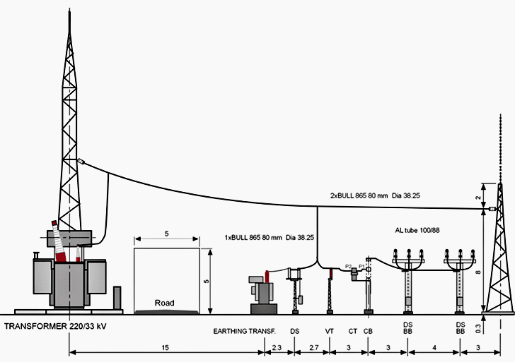
The following figure shows an application where the combined station auxiliary and system- earthing transformer is supplied directly from a main power transformer’s (220/33 kV) low- voltage side.

Figure 1 shows the auxiliary transformer’s physical placement as a part of the bay layout. Since the 33 kV side of a 220/33 kV power transformer is delta-connected, thus not offering a point for system earthing, the station auxiliary transformer is also serving as a system-earthing connection point.
The station auxiliary transformer has a connection group of ZNyn. The zigzag-connected primary winding provides the 33 kV system earthing point. By its nature, the zigzag connection provides also means to limit the earth fault currents into desired level.
The zero-sequence impedance of a zigzag winding can be influenced, within certain limits, by the transformer design.
When the ZNyn-connected earthing transformer is used for low voltage AC-power supply, the magnitude of the available earth fault current on the low voltage side has to be checked, since the zero-sequence reactance of the transformer can limit the current to an unacceptably low value.

AC Auxiliary System Earthing //
The primary AC auxiliary system typically uses effectively direct grounded system, having all the supply points connected to earth. Affected by the legislation in each country, the system is either utilizing the 4-wire or 5-wire principle.
The residual-current protection measures the sum current in all of the phases and the neutral. The sum current must be zero during normal operation. During a system insulation fault, the sum current will rise and the residual current protection switch will open, separating (de-energizing) the section behind the measurement point from the rest of the system.
A typical operating current for residual switch is either 30mA or 300mA, the first being used for human protection and the latter for fire protection.

Reference // ABB’s Distribution Automation Handbook – Elements of power distribution systems