
What affects the operating temperature within LV switchgear
Maximum ambient condition
BS EN 60439 states a maximum indoor ambient temperature of 40ºC, a maximum daily average of 35ºC and a minimum ambient of -5ºC.
As a general guidance rule, the temperature within the low voltage switchgear should not exceed 50/55ºC. If Switchroom/Plant room ambients are typically considered to be up to 25°C this relates to a 25/30K rise above ambient. In the maximum ambient condition of 40ºC, this relates to a 10/15K rise above ambient.
The sources of heat within the low voltage switchgear will be:
- Heat liberated by the copperwork and cabling.
- Heat liberated by the devices.
- Heat liberated by eddy currents and magnetic losses.
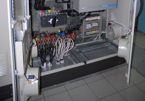
A LV switchgear accommodates a number of devices in a configuration that relates to the scheme requirements. The enclosure and compartments within it provide the operating environment for each device.
Most devices e.g. circuit breakers, fuse switches, contactors etc. have been Type Tested in free air or “other enclosures”.
When enclosed within an LV switchgear compartment the heat liberated may adequately dissipate by convection and radiation from the “walls” of the enclosure and by heat sink via the conductors. It may however be necessary to assist the liberation to atmosphere by forced ventilation.
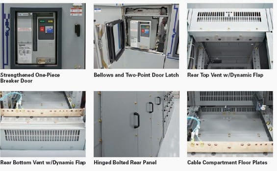
LV switchgear compartments (photo credit: Eaton)
Devices, which invariably require such measures, have by experience been found to be:
- ACB’s above 2,500A
- PFC Capacitor Banks
- Variable Speed Drives
- Motor Starting Resistors
- Power Transformers
Natural ventilation via louvres and/or mesh screens are the simplest and most cost effective measure of controlling temperature rise provided that I.P. ratings are agreed with the client.
The problems arising from eddy currents and magnetic losses are generally overcome by common good practice in the selection of appropriate non-ferrous materials and the avoidance of ferrous metal “magnetic loops” being created in structures in close proximity to conductors or groups of conductors where phase/neutral balance may not prevail.
The subject of these sources of heat is often considered as one but is in fact two separate issues.
Eddy Current heating results from the I2R losses of induced currents circulating in metalwork, which is not part of the defined conductor system. The use of non magnetic, low resistance materials such as Aluminium and Brass for single core cable gland plates and equipment mounting back plates (e.g. for circuit breakers above 630A) will reduce this source of heat and is advisable.
Typical hysteresis loop and magnetic domain morphology og ferromagnetic materials (illustration credit: electronenergy.com)
Magnetic Heating results from the energy dissipated through each cycle of magnetization and de magnetization of a ferrous material (hysteresis loss) and relates to the metalurgical specification of the material used.
Ferrous metal “magnetic loops” around single conductors or groups of conductors that do not produce a magnetic nil balance can bring about additional problems to those mentioned above by virtue of the fact that currents are circulating in metallic structures and joints in them that are not designed as conductor systems. These currents can be of extremely high magnitude, particularly during short-term load inrush transients and during short circuit conditions.
Such high current circulations through joints in the structures can result in arcing / sparking at such joints. The arcing can produce an ionised gaseous state in a region close to the main conductors / busbars and precipitate a most catastrophic flashover and destructive failure in this zone of the switchboard.
In situations where mechanical support is required between conductors, non-magnetic materials and sometimes non-metallic materials, have to be applied.
Forced ventilation with fans
Forced ventilation via fan(s) will have to be considered if natural ventilation will not adequately maintain an acceptable environment for the device(s). Fans should be arranged to provide positive pressure (blowing in at low level) with exhaust air discharging at high level.
It is generally advisable to use fans with integral louver/filter housings regardless of the I.P. requirements.
Anti-condensation control may have to be incorporated either resulting from specified requirements or if the operating environment requires it. This may be catered for by thermostatically controlled heaters and/or ventilation.
Special anti-condensation paint on internal surfaces is also effective in some cases.
Reference: Technical Considerations in the Specification of LV Switchboards – AF SWITCHGEAR & CONTROL PANELS LIMITED