Quantcast
Channel: EEP – Electrical Engineering Portal
Viewing all 1430 articles
Browse latest View live

Qatar General Electricity and Water Corporation – Recommendations for Safety Clearance

$
0
0
Qatar General Electricity and Water Corporation - Recommendations for Safety Clearance

Qatar General Electricity and Water Corporation (Kahramaa) has awarded Leighton Contracting Qatar, a subsidiary of Australia’s HLG, the contract to carry out the work at Al Duhail and Umm Qarn reservoir and pumping stations. Qatar will build nine six million gallon reservoirs and one 25 million gallon reservoir. (photo from bigprojectme.com)

Minimum Safety Clearance of Pipelines from Electrical Tower

ServiceVertical Clearance (Min)
Water Line (to cross below EHV cable level)0.5 Meter
Sewerage Mains (to cross below EHV cable level)1.0 Meter
Drainage Mains (to cross below EHV cable level)0.5 Meter
Gas pipes0.6 Meter
Telephone lines0.5 Meter
LV / 11kV cables0.5 Meter

Safety Clearance for Excavation of Land

Voltage kVMin. Distance
380/220V0.5 Meter
20KV2 Meter
63KV7 Meter
132KV10 Meter
230KV and above20 Meter

Distance between underground power cables to wall of gas pipelines in parallel routes

Voltage kVMin. Horizontal DistanceMin. Vertical Distance
380/220V1 Meter0.5 Meter
20KV2 Meter1 Meter
63KV3 Meter1.5 Meter

(B) Outside of Towns

Distance between Tower’s foundation to Pipeline in parallel and intersections

Voltage KVMin. Distance in Parallel Route
(Up to 5 Km)
Min. Distance in Parallel Route
(Above 5 Km)
20KV20 Meter30 Meter
63KV30 Meter40 Meter
132KV40 Meter50 Meter
230KV50 Meter60 Meter
400KV60 Meter60 Meter

Distance between overhead lines to gas pipelines at intersections

Voltage KVMin. Distance
20KV8 Meter
63KV9 Meter
132KV10 Meter
230KV11 Meter
400KV12 Meter

Distance between Tower’s foundations to gas pipelines at intersections

 Voltage KVMin. Distance
20KV20 Meter
63KV and higher30 Meter

Right Of Way (R.O.W) From Roads

HighwayDistance
High Way: (38 meter from one side of Central Line of Highway)76 Meter
First Class State Road=(22.5 meter from one side of Central Line of Highway)45 Meter
Second Class State Road=(17.5 meter from one side of Central Line of Highway)35 Meter
Third Class State Road =(12.5 meter from one side of Central Line of Highway)25 Meter
Forth Class State Road=(7.5 meter from one side of Central Line of Highway)15 Meter

General Electrical Safety Clearance

Voltage KVDescriptionDistance
Up to 11 KVAt points where the lines cross roads or railwaysMin 6 Meter Height
Up to 11 KVParallel to the roadsMin 5.5 Meter Height
Up to 11 KVLines cross totally desert regions where no traffic is possibleMin 5.5 Meter Height
20 KV to 66 KVAll LocationMin 6 Meter Height
Up to 11 KVConductor JointNo joint shall be closer than 3 meters to a point of support
33 KV & 66 KVConductor JointNo tension joints shall be used unless specially approved.

Definition of Harmonics and Their Origin

$
0
0
Definition of harmonics and their origin

Definition of harmonics and their origin

Distortion of a sinusoidal signal

The Fourier theorem states that all non-sinusoidal periodic functions can be represented as the sum of terms (i.e. a series) made up of:

  1. A sinusoidal term at the fundamental frequency,
  2. Sinusoidal terms (harmonics) whose frequencies are whole multiples of the fundamental frequency,
  3. A DC component, where applicable.
The nth order harmonic (commonly referred to as simply the nth harmonic) in a signal is the sinusoidal component with a frequency that is n times the fundamental frequency.

The equation for the harmonic expansion of a periodic function is presented below:

Equation for the harmonic expansion

where:

Yo - value of the DC component, generally zero and considered as such hereinafter,
Yn - rms value of the nth harmonic,
ω – angular frequency of the fundamental frequency,
ϕn – displacement of the harmonic component at t = 0.

Example of signals (current and voltage waves) on the French electrical distribution system:

  • The value of the fundamental frequency (or first order harmonic) is 50 Hertz (Hz),
  • The second (order) harmonic has a frequency of 100 Hz,
  • The third harmonic has a frequency of 150 Hz,
  • The fourth harmonic has a frequency of 200 Hz, etc.

A distorted signal is the sum of a number of superimposed harmonics. Figure 1 shows an example of a current wave affected by harmonic distortion.

Example of a current containing harmonics and expansion of the overall current

Figure 1 - example of a current containing harmonics and expansion of the overall current into its harmonic orders 1 (fundamental), 3, 5, 7 and 9

Representation of harmonics: the frequency spectrum

The frequency spectrum is a practical graphical means of representing the harmonics contained in a periodic signal.

The graph indicates the amplitude of each harmonic order. This type of representation is also referred to as spectral analysis. The frequency spectrum indicates which harmonics are present and their relative importance.

Figure 2 shows the frequency spectrum of the signal presented in figure 1.

Spectrum of a signal comprising a 50 Hz fundamental and harmonic orders

Figure 2 - spectrum of a signal comprising a 50 Hz fundamental and harmonic orders 3 (150 Hz), 5 (250 Hz), 7 (350 Hz) and 9 (450 Hz)

Origin of harmonics

Devices causing harmonics are present in all industrial, commercial and residential installations. Harmonics are caused by non-linear loads.


Definition of non-linear loads

A load is said to be non-linear when the current it draws does not have the same wave form as the supply voltage.


Examples of non-linear loads

Devices comprising power electronics circuits are typical non-linear loads. Such loads are increasingly frequent and their percentage in overall electrical consumption is growing steadily.

Examples include:
  • Industrial equipment (welding machines, arc furnaces, induction furnaces, rectifiers),
  • Variable-speed drives for asynchronous and DC motors,
  • Office equipment (PCs, photocopy machines, fax machines, etc.),
  • Household appliances (television sets, microwave ovens, fluorescent lighting, etc.),
  • UPSs.

Saturation of equipment (essentially transformers) may also cause non-linear currents.


Disturbances caused by non-linear loads, i.e. current and voltage harmonics

The supply of power to non-linear loads causes the flow of harmonic currents in the distribution system.

Voltage harmonics are caused by the flow of harmonic currents through the impedances of the supply circuits (e.g. transformer and distribution system a whole in figure 3).

Single-line diagram showing the impedance of the supply circuit for h-order harmonic

Figure 3 - single-line diagram showing the impedance of the supply circuit for h-order harmonic


Note that the impedance of a conductor increases as a function of the frequency of the current flowing through it. For each h-order harmonic current, there is therefore an impedance Zh in the supply circuit.

The h-order harmonic current creates via impedance Zh a harmonic voltage Uh, where Uh = Zh x Ih, i.e. a simple application of Ohm’s law. The voltage at B is therefore distorted and all devices supplied downstream of point B will receive a distorted voltage.

Distortion increases in step with the level of the impedances in the distribution system, for a given harmonic current.


Flow of harmonics in distribution systems

To better understand harmonic currents, it may be useful to imagine that the non-linear loads reinject harmonic currents upstream into the distribution system, in the direction of the source.

Figures 4a and 4b show an installation confronted with harmonic disturbances. Figure 4a shows the flow of the fundamental 50 Hz current, whereas in 4b, the h-order harmonic current is presented.

Diagram of an installation supplying a non-linear load

Figure 4a - diagram of an installation supplying a non-linear load, showing only the fundamental 50 Hz current


Diagram of the same installation, showing only the phenomena related to the h-order harmonic

Figure 4b - diagram of the same installation, showing only the phenomena related to the h-order harmonic


Supply of this non-linear load causes the flow in the distribution system of current I50Hz (shown in figure 4a) to which is added each of the harmonic currents Ih (shown in figure 4b) corresponding to each harmonic (order h).

Resource: Harmonic Detection and Filtering – Schneider Electric

Differences between Shunt Reactor and Power Transformer

$
0
0
Differences between Shunt Reactor and Power Transformer

Differences between Shunt Reactor and Power Transformer

Main Differences

Shunt Reactor and Transformer both appear similar in construction. Reactors are also often equipped with Fans for cooling similar to Power Transformers.

However, there are major differences between the two. While a Power Transformer is designed for efficient power transfer from one voltage system to another, a shunt reactor is intended only to consume reactive VArs (or in other words it can be stated as to produce lagging VArs).

Thus, there are more than one winding on a Power Transformer with magnetic core which carry the mutual flux between the two. In reactor there is just one winding. The core is not therefore meant only to provide a low reluctance path for flux of that winding to increase the Inductance.

In case of a Power Transformer, primary Ampere-Turns (AT) is sum of exciting AT and secondary AT. AT loss (in winding resistance, eddy loss and hysteric loss) is kept to as minimum as possible. Exciting AT is small compared with the secondary AT. Rated current is based on the load transfer requirement.

Detailed view of an iron core divided by air gaps

Detailed view of an iron core divided by air gaps

Magnetizing current is small and is negligible value when compared with the secondary rated current. Further, since mutual flux is main flux which results in transformation, leakage flux is kept small and will be based on fault current limitation.

In case of a Shunt Reactor due to absence of other windings, all primary AT is equal to the exciting AT. Similar to a Power Transformer, loss in AT (in winding resistance, eddy current and hysteresis) are also kept to minimum by design. Magnetizing AT is major component of a Shunt Reactor. Reactor magnetizing current is its rated current.

Since a Shunt Reactor magnetizing current is large, if it is designed with Iron alone as a Power Transformer, there will be large hysteresis loss. Air gaps in Iron core are provided in a Shunt Reactor to reduce this loss and to minimize the remanent flux in the core.

Thus a Shunt Reactor may also be constructed without iron (air-core).

By construction, a Shunt Reactor can be oil immersed or dry type for both with and without iron core.

Dry type Reactors are constructed as single phase units and are thus arranged in a fashion to minimize stray magnetic field on surrounding (in the absence of metallic shielding). When such an arrangement is difficult, some form of magnetic shielding is required and designed with care to minimize eddy current loss and arcing at any joints within the metallic loops. One of the advantages of dry type reactor is absence of inrush current.

Oil immersed reactors can be core-less or with gapped iron core. These are either single phase or three phase design with or without fan cooling. These are installed within tanks which hold oil & act as metallic magnetic shields.

In some cases, a Shunt Reactor may have additional small capacity winding which can provide power for small station power loads. Since Shunt Reactor rating is normally based on MVAr rating, this added station load VA shall be accounted for in designing the Reactor for such applications.

Types of shunt reactors

Types of shunt reactors


Shunt reactors are used in high voltage systems to compensate for the capacitive generation of long overhead lines or extended cable networks.


The reasons for using shunt reactors are mainly two

The first reason is to limit the overvoltages and the second reason is to limit the transfer of reactive power in the network. If the reactive power transfer is minimized i. e. the reactive power is balanced in the different part of the networks, a higher level of active power can be transferred in the network.

Reactors to limit overvoltages are most needed in weak power systems, i.e. when network short-circuit power is relatively low.

Voltage increase in a system due to the capacitive generation is:

ΔU(%) = QC x 100 / Ssh.c

where:

Qc is the capacitive input of reactive power to the network
Ssh.c is the short circuit power of the network

With increasing short circuit power of the network the voltage increase will be lower and the need of compensation to limit over-voltages will be less accentuated.

Reactors to achieve reactive power balance in the different part of the network are most needed in heavy loaded networks where new lines cannot be built because of environmental reasons. Reactors for this purpose mostly are thyristor controlled in order to adapt fast to the reactive power required.

Especially in industrial areas with arc furnaces the reactive power demand is fluctuating between each half cycle.

In such applications there are usually combinations of:
  1. Thyristor controlled reactors (TCR) and
  2. Thyristor switched capacitor banks (TSC).

These together makes it possible to both absorb, and generate reactive power according to the momentary demand.

Four leg reactors also can be used for extinction of the secondary are at single-phase reclosing in long transmission lines. Since there always is a capacitive coupling between phases, this capacitance will give a current keeping the are burning, a secondary arc.

By adding one single-phase reactor in the neutral the secondary arc can be extinguished and the single-phase auto-reclosing successful.

Resource: Shunt Reactors and Shunt Reactor Protection - S.R. Javed Ahmed

Design of Overhead Transmission Line Foundation

$
0
0
Design of Overhead Transmission Line Foundation

Design of Overhead Transmission Line Foundation

General

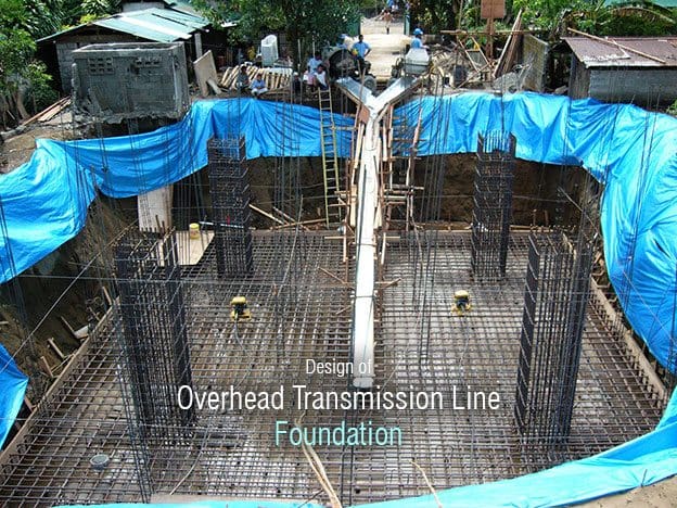
The foundation is the name given to the system which transfers to the ground the various steady state (dead) and variable (live) loads developed by the transmission tower and conductors. Foundations may be variously subjected to compressive or bearing forces, uplift and shear forces, either singly or as a result of any combination of two or three of the forces.

Usually, the limiting design load with transmission line foundations is the uplift load.

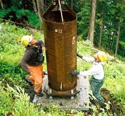
Sunrise caps foundation of transmission tower

Sunrise Powerlink Steel Cap Micropile Foundation (Patent Pending)

In this respect, there is a major difference between the design of foundations for transmission lines compared to the design of foundations for most normal civil engineering structures.

Accordingly, the amount of literature describing design techniques for overhead line foundations is relatively small compared to the literature available for more traditional civil engineering foundation design practice.

The selected foundation design for a particular tower must provide an economical, reliable support for the life of the line. The foundation must be compatible with the soil and must not lose strength with age.

With the progressive increase in transmission system voltages there has been a related increase in foundation sizes and it is worth noting that with a typical quad conductor 500 kV line, single leg uplift and ultimate compression loads of 70 or 80 tonnes are usual for suspension towers.

With tension towers, ultimate loads of 200 or 300 tonnes are often developed.

In ground of poor load-bearing capacity the dimensions of foundations become considerable.

In the past, it was often acceptable to ‘over-design’ foundations to allow for uncertainties in the soil characteristics. With the large sizes of foundations for EHV and UHV transmission it is obvious that significant economies can be made in producing foundation designs to exactly match the soil conditions.

Increasingly, transmission lines are routed through areas of poor ground conditions, often for reasons of amenity. This results in the need for the use of special, generally larger, foundations.

The logistical problems of installing large foundations, often in difficult ground conditions, must be taken into account when considering foundation design.


Types of ground

Micropile Foundation for Transmission Line

Micropile Foundation for Transmission Line

The ground in which the foundations are installed can vary from igneous, sedimentary or metamorphic rock, noncohesive soils, sand or gravel to cohesive soil, usually clays. Equally, soils with a high organic content, for example peat, can also prevail. Composite soils will also be found, and examples of these are sandy gravels and silty sand or sandy peat.

Fundamental to the proper design of foundations is an accurate series of soil tests to determine the range of soil types for which the foundation designs will be required. It is good practice to carry out soil tests at a rate of 1 in 5 tower sites.

This is generally sufficient to enable an accurate forecast of the range of soil types to be established.

It should be pointed out, however, that with large towers having 15 or 20 m square bases, occasionally each of the four legs of a tower may be founded in four different types of ground.

Types of foundation

There are seven basic types of tower foundations:

  1. Steel grillage
  2. Concrete spread footing
  3. Concrete auger or caisson
  4. Pile foundation
  5. Rock foundation
  6. Raft foundation
  7. Novel foundations.

Foundation calculations

There are a number of methods of calculation of foundation uplift and bearing capacity. For the purposes of this article, however, we will confine ourselves to a simple approach which must be treated with care. Nevertheless, the methods indicated will give reasonably accurate results for the relatively shallow foundations which are normally employed with transmission line towers.

A shallow foundation is usually defined as one in which the breadth of the pad is greater than the setting depth.

It is usual to calculate the uplift capacity of a foundation as being equal to the mass of soil contained in the frustum developed between the base of the foundation pad and the soil surface.

The angle of the face of the frustum to the vertical is usually designated @ and will vary from 35° to 40° in rock, to 25° in good homogeneous hard clay to zero in saturated noncohesive ground. The soil density will vary from just over 2000 kg/m3 for homogeneous rock to about 1600 kg/m3 for soil with normal moisture content to about 800 or 900 kg/m3 in the case of ground subjected to water uplift.

Methods of calculation of uplift capacity are shown below.


Undercut Pyramid Foundation

Undercut pyramid foundation calculation

Undercut pyramid foundation calculation

Concrete Auger Foundation

Concrete auger foundation calculation

Concrete auger foundation calculation


Resource: High voltage engineering and testing – Hugh M. Ryan (Buy this book at Amazon)

Purpose of Equipotential Bonding

$
0
0
Purpose of Equipotential bonding

Purpose of Equipotential bonding


Equipotential bonding is essentially an electrical connection maintaining various exposed conductive parts and extraneous conductive parts at substantially the same potential.

An earthed equipotential zone is one within which exposed conductive parts and extraneous conductive parts are maintained at substantially the same potential by bonding, such as that, under fault conditions, the difference in potential between simultaneously accessible exposed and extraneous conductive parts will not cause electric shock.

Bonding is the practice of connecting all accessible metalwork – whether associated with the electrical installation (known as exposed metalwork) or not (extraneous metalwork) – to the system earth.

In a building, there are typically a number of services other than electrical supply that employ metallic connections in their design. These include water piping, gas piping, HVAC ducting, and so on. A building may also contain steel structures in its construction. We have seen earlier in this chapter that when an earth fault takes place in an installation, the external conducting surfaces of the installation and the earth mass in the vicinity may attain higher potential with reference to the source earth.

There is thus a possibility that a dangerous potential may develop between the conducting parts of non-electrical systems including building structures and the external conducting parts of electrical installations as well as the surrounding earth.

This may give rise to undesirable current flow through paths that are not normally designed to carry current (such as joints in building structures) and also cause hazardous situations of indirect shock.

It is therefore necessary that all such parts are bonded to the electrical service earth point of the building to ensure safety of occupants. This is called equipotential bonding.

There are two aspects to equipotential bonding: the main bonding where services enter the building and supplementary bonding within rooms, particularly kitchens and bathrooms.

Main bonding should interconnect the incoming gas, water and electricity service where these are metallic but can be omitted where the services are run in plastic, as is frequently the case nowadays. Internally, bonding should link any items, which are likely to be at earth potential or which may become live in the event of a fault and which are sufficiently large that they can contact a significant part of the body or can be gripped.

Small parts, other than those likely to be gripped, are ignored because the instinctive reaction to a shock is muscular contraction, which will break the circuit.


Bonding Metal Piping Systems


In each electrical installation, main equipotential bonding conductors (earthing wires) are required to connect to the main earthing terminal for the installation of the following:

  • Metal water service pipes
  • Metal gas installation pipes
  • Other metal service pipes and ducting
  • Metal central heating and air-conditioning systems
  • Exposed metal structural parts of the building
  • Lightning protection systems.

It is important to note that the reference above is always to metal pipes. If the pipes are made of plastic, they need not be main bonded.

If the incoming pipes are made of plastic but the pipes within the electrical installation are made of metal, the main bonding must be carried out, the bonding being applied on the customer side of any meter, main stopcock or insulating insert and of course to the metal pipes of the installation.

Such bonding is also necessary between the earth conductors of electrical systems and those of separately derived computer power supply systems, communication, signal and data systems and lightning protection earthing of a building.
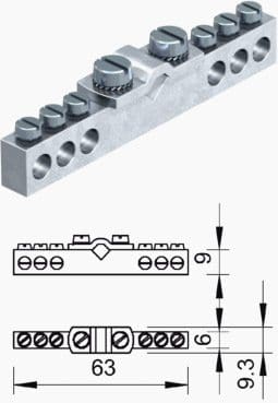
Equipotential bonding terminal for bathroom (OBO)

Equipotential bonding terminal for bathroom (OBO)

Many equipment failures in sensitive computing and communication equipment are attributable to the insistence of the vendors to keep them separated from the electrical service earth. Besides equipment failures, such a practice also poses safety hazards particularly when lightning discharges take place in the vicinity.

In such cases, large potential difference can arise for very short periods between metal parts of different services unless they are properly bonded. Some of the case studies in a later chapter deal with this issue.

If the incoming services are made of plastic and the piping within the building is of plastic, then no main bonding is required. If some of the services are of metal and some are plastic, then those that are of metal must be main bonded.

Supplementary or additional equipotential bonding (earthing) is required in locations of increased shock risk. In domestic premises, the locations identified as having this increased shock risk are rooms containing a bath or shower (bathrooms) and in the areas surrounding swimming pools.

There is no specific requirement to carry out supplementary bonding in domestic kitchens, washrooms and lavatories that do not have a bath or shower. That is not to say that supplementary bonding in a kitchen or washroom is wrong, but it is not necessary.

For plastic pipe installation within a bathroom, the plastic pipes do not require supplementary bonding, and metal fittings attached to these plastic pipes also would not require supplementary bonding. However, electrical equipment still does require to be bonded and if an electric shower or radiant heater is fitted, they will require supplementary bonding as well.

Supplementary bonding is carried out to the earth terminal of equipment within the bathroom with exposed conductive part. A supplementary bond is not run back to the main earth. Metal window frames are not to be supplementary bonded unless they are electrically connected to the metallic structure of the building.

Metal baths supplied by metal pipes do not require supplementary bonding if all the pipes are bonded and there is no other connection of the bath to earth.

All bonding connections must be accessible and labeled:

SAFETY OF ELECTRICAL CONNECTION – DO NOT REMOVE!

Resource: Grounding, bonding, shielding and surge protection – G. Vijayaraghavan
(Buy this book at Amazon)

Introduction to Static Protection Relays

$
0
0
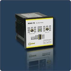
RSR-72 Static relay for motor re-start and reacceleration

The RSR-72 type relay for re-start and reacceleration is deigned to perform the automatic motor restarting, after control and protection device opening, as a consequence of a momentary line voltage interruption or drop-out.

The term ‘static’ implies that the relay has no moving parts. This is not strictly the case for a static relay, as the output contacts are still generally attracted armature relays. In a protection relay, the term ‘static’ refers to the absence of moving parts to create the relay characteristic.

Introduction of static relays began in the early 1960’s. Their design is based on the use of analogue electronic devices instead of coils and magnets to create the relay characteristic. Early versions used discrete devices such as transistors and diodes in conjunction with resistors, capacitors, inductors, etc., but advances in electronics enabled the use of linear and digital integrated circuits in later versions for signal processing and implementation of logic functions.

While basic circuits may be common to a number of relays, the packaging was still essentially restricted to a single protection function per case, while complex functions required several cases of hardware suitably interconnected. User programming was restricted to the basic functions of adjustment of relay characteristic curves.

They therefore can be viewed in simple terms as an analogue electronic replacement for electromechanical relays, with some additional flexibility in settings and some saving in space requirements. In some cases, relay burden is reduced, making for reduced CT/VT output requirements.

A number of design problems had to be solved with static relays. In particular, the relays generally require a reliable source of d.c. power and measures to prevent damage to vulnerable electronic circuits had to be devised. Substation environments are particularly hostile to electronic circuits due to electrical interference of various forms that are commonly found (e.g. switching operations and the effect of faults).

Selection of static relays

Figure 1 - Selection of static relays

While it is possible to arrange for the d.c. supply to be generated from the measured quantities of the relay, this has the disadvantage of increasing the burden on the CT’s or VT’s, and there will be a minimum primary current or voltage below which the relay will not operate. This directly affects the possible sensitivity of the relay.

So provision of an independent, highly reliable and secure source of relay power supply was an important consideration.

To prevent maloperation or destruction of electronic devices during faults or switching operations, sensitive circuitry is housed in a shielded case to exclude common mode and radiated interference. The devices may also be sensitive to static charge, requiring special precautions during handling, as damage from this cause may not be immediately apparent, but become apparent later in the form of premature failure of the relay.

Therefore, radically different relay manufacturing facilities are required compared to electromechanical relays. Calibration and repair is no longer a task performed in the field without specialised equipment.

Figure 1 above shows examples of simple and complex static relays and Figure 2 shows the circuit board for a simple static relay.

Circuit board of static relay

Figure 2 - Circuit board of static relay


Advantages of Static Relays

Static relays in general possess the following advantages:

  1. Low burden on current and voltage transformers, since the operating power is. in many cases, from an auxiliary d.c. supply.
  2. Absence of mechanical inertia and bouncing contacts, high resistance to shock and vibration.
  3. Very fast operation and long life.
  4. Low maintenance owing to the absence of moving parts and bearing friction.
  5. Quick reset action and absence of overshoot.
  6. Ease of providing amplification enables greater sensitivity.
  7. Unconventional characteristics are possible – the basic building blocks of semiconductor circuitry permit a greater degree of sophistication in the shaping of operating characteristics, enabling the practical utilization of relays with operating characteristics more closely approaching the ideal requirements.
  8. The low energy levels required in the measuring circuits permit miniaturization of the relay modules.

Resources: Network Protection & Automation Guide – Areva; Power System Protection: Static Relays by T. S. Madhava Rao

Surge Protection of Electronic Equipment

$
0
0
Surge Protection of Electronic Equipment

Surge Protection of Electronic Equipment

Introduction

Generally, power circuits have components that have large thermal capacities, which make it impossible for them to attain very high temperatures quickly except during very large or long disturbances. This requires correspondingly large surge energies. Also, the materials that constitute the insulation of these components can operate at temperatures as high as 200 ºC at least for short periods.

Electronic circuits, on the other hand, use components that operate at very small voltage and power levels. Even small magnitude surge currents or transient voltages are enough to cause high temperatures and voltage breakdowns.

This is so because of the very small electrical clearances that are involved in PCBs and ICs (often in microns) and the very poor temperature withstanding ability of many semiconducting materials, which form the core of these components.

As such, a higher degree of surge protection is called for if these devices have to operate safely in the normal electrical system environment.

Thus comes the concept of surge protection zones (SPZs).

According to this concept, an entire facility can be divided into zones, each with a higher level of protection and nested within one another.

As we move up the SPZ scale, the surges become smaller in magnitude, and protection better.
  • Zone 0: This is the uncontrolled zone of the external world with surge protection adequate for high-voltage power transmission and main distribution equipment.
  • Zone 1: Controlled environment that adequately protects the electrical equipment found in a normal building distribution system.
  • Zone 2: This zone has protection catering to electronic equipment of the more rugged variety (power electronic equipment or control devices of discrete type).
  • Zone 3: This zone houses the most sensitive electronic equipment, and protection of highest possible order isprovided (includes computer CPUs, distributed control systems, devices with ICs, etc.).


The SPZ principle is illustrated in Figure 1.

Zoned protection approach

Figure 1 - Zoned protection approach


We call this the zoned protection approach and we see these various zones with the appropriate reduction in the order of magnitude of the surge current, as we go down further and further into the zones, into the facility itself.

Notice that in the uncontrolled environment outside of our building, we would consider the amplitude of say, 1000 A.

As we move into the first level of controlled environment, called zone 1, we would get a reduction by a factor of 10 to possibly 100 A of surge capability. As we move into a more specific location, zone 2, perhaps a computer room or a room where various sensitive hardware exist, we find another reduction by a factor of 10.

Finally, within the equipment itself, we may find another reduction by a factor of 10, the effect of this surge being basically one ampere at the device itself. The IEEE C62.41 indicates a similar but slightly differing approach to protection zones.

The idea of the zone protection approach is to utilize the inductive capacity of the facility, namely the wiring, to help attenuate the surge current magnitude, as we go further and further away from the service entrance to the facility.

The transition between zones 0 and 1 is further elaborated in Figure 2. Here we have a detailed picture of the entrance into the building where the telecommunications, data communications and the power supply wires all enter from the outside to the first protected zone.

Notice that the surge protection device (SPD) is basically stripping any transient phenomena on any of these metallic wires, referencing all of this to the common service entrance earth even as it is attached to the metallic water piping system.

The transition from zone 0 to zone 1

Figure 2 - The transition from zone 0 to zone 1


Similarly, the protection for zone 2 at the transition point from zone 1 is shown in Figure 3.

Here as we address the discrete level between the first level of controlled zone 1 and perhaps the plug-in device taking it into the zone 2 location, we can see surge protection devices are available that handle the telecommunications, data and different types of physical plug connections for each, including both the RJ type of telephone plug as well as coaxial wiring.

The transition from zone 1 to zone 2

Figure 3 - The transition from zone 1 to zone 2


This is a common design error where there are two points of entry and therefore two earthing points are established for the AC power and telecommunication circuits.

The use of the TVSS devices at each point is highly beneficial in controlling the line-to-line and line-to-earth surge conditions at each point of entry, but the arrangement cannot perform this task between points of entry.

This is of paramount importance since the victim equipment is connected between the two points. Hence, a common-mode surge current will be driven through the victim equipment between the two circuits despite the presence of the much-needed TVSS.

The minimal result of the above is corruption of the data and maximally, there may be fire and shock hazard involved at the equipment.

No matter what kind of TVSS is used in the above arrangement nor how many and what kind of additional individual, dedicated earthing wires, etc. are used, the stated problem will remain much as discussed above. Wires all possess self-inductance and because of −e = L dI/dT conditions cannot equalize potential across themselves under normal impulse /surge conditions.

Such wires may self-resonate in quarter-waves and odd-multiples thereof, and this is also harmful.This also applies to metal pipes, steel beams, etc.

Earthing to these nearby items may be needed to avoid lightning side-flash, however.


Achieving Graded Surge Protection


From the above, it will be clear that the type of surge protection depends on the type of zone and the equipment to be protected. We will further illustrate this by example, as we proceed from the uncontrolled area of zone 0.

Let us begin by talking about what happens when a lightning strike hits an overhead distribution line.

Here in Figure 4, we see the picture of the thunderstorm cloud discharging onto the distribution line and the points ofapplication of a lightning arrestor by the power company at points #1 and #2. We notice that the operating voltage here is 11 000 volts on the primary line and the transformer has a secondary voltage of 380/400 V typically serving the consumer.

We need to understand what is known as traveling wave phenomena. When the lightning strike hits the power line, the powerline’s inherent construction makes it capable to withstand as much as 95 000 V for its insulation system.

Protections in zone 0

Figure 4 - Protections in zone 0


We call this the basic impulse level (BIL).

Most of the 11 000-V construction equipment would have a BIL rating of 95 kV. This says to us that the wire insulation, the cross-arms and all of the other parts, which are nearby to the current-carrying conductors, are able to withstand this high voltage.

Traveling waves and sparks over the lightning arrestor applied on a 11 000-V line might have a spark-over characteristic of approximately 22 000 V. This high level of spark-over protection is to enable the lightning arrestor to wait until the peak of the 11 000-V operating wave shape is exceeded before discharging the energy into the earth.

The peak of the 11 000-V RMS wave would be somewhere in the neighborhood of 15 000 V. As the voltage comes to the 22 000-V level and then stays there as the lightning arrestor performs its discharge, that voltage waveform travels on the power line moving very fast to all points of the line. At places where there is discontinuity to the electric line, such as points #3 or #4 in our chart, the traveling wave will go in at 22 000 V and then will double and start back down the line at 44 000 V.

This type of phenomenon is known as reflection of the traveling wave and it occurs at open parts of the circuit or even the primary of transformers. When the primary of our distribution transformer serving the building achieves 44 000 V, the secondary supplying the building is going to have an over-voltage condition on it.

Thus, points #5 and #6 on our chart require us to think in terms of some type of lightning-protective devices at the secondary of the transformer, the service entrance to the building and then further on into the building such as point #6 for the sensitive equipment to be fully protected in this facility.

Resource: Grounding, bonding, shielding and surge protection – G. Vijayaraghavan
(Buy this book at Amazon)

Testing and Commissioning of Metal-Clad Switchgear

$
0
0
Distribution substation - 20/04kV MCset metal-clad switchgear  (Schneider Electric)

Distribution substation - 20/04kV MCset metal-clad switchgear (Schneider Electric)


Electrical testing and commissioning of Metal-Clad switchgear is essential to the safe start for the first time, regardless of its size, type or industry.

This article cover testing and start-up / commisioning procedures for all the components of medium voltage switchgear like circuit breaker, busbars, instrument transformers (current/voltage), disconnect and grounding switches etc.


1.1. Objective

To verify the physical condition and proper connections of bus bar.


1.2. Test Equipment Required:

• Insulation test (Megger)
• Micro ohmmeter
• High voltage tester
• Torque wrench


1.3. Test Procedure:

1.3.1. Mechanical Checks and Visual Inspection:

• Inspect switchgear and all components for any physical damage / defects.
• Check nameplate information for correctness.
• Inspect enclosures for proper alignment, foundation fixing, and grounding and vermin entry.
• Inspect all covers, panels’ section and doors for paintwork and proper fit.
• Check all the transport locks are removed.
• Check for smooth and proper movementof racking mechanisms, shutter, rollers, rails and guides.
• Check proper alignment of the primary and secondary contacts.
• Check operation of all mechanical interlocks.
• Check tightness of all bolted connections.
• Check for correct phasing connection of bus bar.
• Perform mechanical check and visual inspection for breaker / Contactor as per section.
• Perform mechanical check and visual inspection for instrument transformers as per section
• Perform mechanical check and visual inspection on all disconnect / grounding switches as per section.


1.3.2. Insulation Resistance Test:

It includes panel enclosure, busbar, CT and circuit breaker. The following precautions should be taken care, before starting the testing.

A visual inspection will be made to ensure the surface dust and moisture has been removed from the component under test. Ensure the component is isolated from other connected system, which may feed back to other components or circuits not under test.

On testing, voltage shall be applied between one phase and other phases connected with ground, testing shall be repeated for other phases as mentioned above. Test voltage limits mentioned in table below:

Rated voltageTest voltage
100-1000V AC/DC1000V DC
>1000 to <5000V AC2500V DC
> 5000V AC5000V DC

1.3.3. Contact Resistance Test:

This test is to confirm the busbar joints are connected properly and verify the tightness.

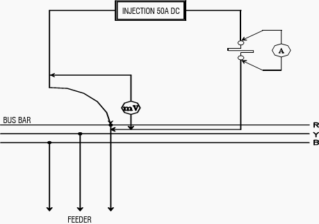
The test connection diagram is as shown in Figure below.

The test shall be done with CBs inserted and closed. Measure the contact dc resistance between panels by injecting 100A DC. This will include busbar joint, CB contact resistance, CB cluster resistance, and CT primary resistance (if applicable).

Limits:

The obtained results should be similar for all phases for each set of measurement. Other influencing factors to be considered, like length of the measured path, rating of the busbar, rating of CB, rating of CT and temperature.

Contact resistance test

Figure 1 - Contact resistance test

1.3.4 High Voltage Test

To determine the equipment is in propercondition to put in service, after installation for which it was designed and to give some basis for predicting whether or not that a healthy condition will remain or if deterioration is underway which can result in abnormally short life.


Test Instruments Required:

• Calibrated AC Hi-pot test set for switchgear with leakage current indicator and overload protection.
• Calibrated DC Hi-pot test set for cables with leakage current indicator and overload protection.


1.4. Applicable Standard

IEC60298: – AC metal enclosed switchgear and control gear for rated voltage above 1KV to 52KV.

Resource: Procedures for Testing and Commissioning of Electrical Equipment – Schneider Electric


Inspection of Ground-Fault Protection Systems

$
0
0
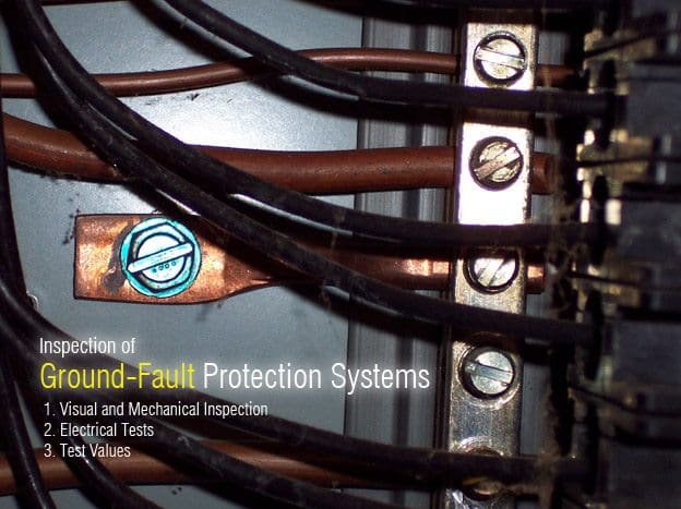
Inspection of Ground-Fault Protection Systems

Inspection of Ground-Fault Protection Systems

The role and functions of Ground Fault Protection

This type of protection is defined by the NEC (National Electrical Code) to ensure protection against fire on electrical power installations.

To ensure protection against fire:
  • The NEC defines the use of an RCD with very low sensitivity called GFP
  • IEC 60 364 standard uses the characteristics of the TT system combined with low or high sensitivity RCDs.

These protections use the same principle.  Fault current measurement using:

  • A sensor that is sensitive to earth fault or residual current (earth fault current)
  • A measuring relay that compares the current to the setting threshold
  • An actuator that sends a tripping order to the breaking unit on the monitored circuit in case the threshold setting has been exceeded.

1. Visual and Mechanical Inspection

  1. Compare equipment nameplate datawith drawings and specifications.
  2. Inspect the components for damage and errors in polarity or conductor routing:
    1. Verify that ground connection is made ahead of the neutral disconnect link and on the line side of any ground fault sensor.
    2. Verify that the neutral sensors are connected with correct polarity on both primary and secondary.
    3. Verify that all phase conductors and the neutral pass through the sensor in the same direction for zero sequence systems.
    4. Verify that grounding conductors do not pass through the zero sequence sensors.
    5. Verify that the grounded conductor is solidly grounded.
  3. Inspect bolted electrical connections for high resistance using one of the following methods:
    1. Use of low-resistance ohmmeter in accordance with Section 7.14.2.
    2. Verify tightness of accessible bolted electrical connections by calibrated torque-wrench method in accordance with manufacturer’s published data or Table 100.12.
    3. Perform thermographic survey in accordance with Section 9.
  4. Verify correct operation of all functions of the self-test panel.
  5. Verify that the control power transformer has adequate capacity for the system.
  6. Set pickup and time-delay settings in accordance with the settings provided in the owner’s specifications. Record appropriate operation and test sequences as required by NFPA 70 National Electrical CodeArticle 230.95.
* Optional

2. Electrical Tests

  1. Perform resistance measurements through bolted connections with a low-resistance ohmmeter,  if applicable, in accordance with Section 7.14.1.
  2. Measure the system neutral-to-ground insulation resistance with the neutral disconnect link temporarily removed. Replace neutral disconnect link after testing.
  3. Perform insulation resistance test on all control wiring with respect to ground. Applied potential shall be 500 volts dc for 300 volt rated cable and 1000 volts dc for 600 volt rated cable. Test duration shall be one minute. For units with solid-statecomponents or control devices that can not tolerate the applied voltage, follow manufacturer’s recommendation.
  4. Perform the following pickup tests using primary injection:
    1. Verify that the relay does not operateat 90 percent of the pickup setting.
    2. Verify pickup is less than 125 percent of setting or 1200 amperes, whichever is smaller.
  5. For summation type systems utilizing phase and neutral current transformers, verify correct polarities by applying current to each phase-neutral current transformer pair.
    This test also applies to molded-case breakers utilizing anexternal neutral current transformer.
    1. Relay should operate when current direction is the same relative to polarity marks in the two current transformers.
    2. Relay should not operate when current direction is opposite relative to polarity marks in the two current transformers.
  6. Measure time delay of the relay at 150% or greater of pickup.
  7. Verify reduced control voltage tripping capability is 55 percent for ac systems and 80 percent for dc systems.
  8. Verify blocking capability of zone interlock systems.

* Optional


3. Test Values

  1. Compare bolted connection resistances to values of similar connections.
  2. Bolt-torque levels should be in accordance with Table 100.12 unless otherwise specified by manufacturer.
  3. Microhm or millivolt drop values shall not exceed the high levels of the normal range as indicated in the manufacturer’s published data. If manufacturer’s datais not available, investigate any values which deviate from similar connections by more than 50% of the lowest value.
  4. System neutral-to-ground insulation shall be a minimum of 1.0 megohm.
  5. Insulation-resistance values for control wiring shall be a minimum of 2.0 megohms.
  6. Relay timing shall be in accordance with manufacturer’s specifications but must be no longer than one second at 3000 amperes.

Ground fault in a High Resistance Grounding System


Resource: 2003 NETA Acceptance Testing Specifications; Ground Fault Protection – Schneider Electric

How are sensitive circuits affected by noise?

$
0
0
How are sensitive circuits affected by noise?

How are sensitive circuits affected by noise? (photo by Jim Hartland at Flickr)

Introduction

Noise is only important if it is measured in relation to the communication signal, which carries the data or information. Electronic receiving circuits for digital communications have a broad voltage range, which determines whether a signal is binary bit ‘1’ or ‘0’.

The noise voltage has to be high enough to take the signal voltage outside these limits for errors to occur.

The power and logic voltages of present day devices have been drastically reduced and at the same time, the speed of these devices has increased with propagation times now being measured in picoseconds. While the speed of the equipment has gone up and the voltage sensitivity has gone down, the noise conditions coming from the power supply side have not reduced at all.

The best illustration that can be given of this condition is to consider where the signal voltage has been and what is happening to it compared to the noise voltage (see Figure 1).

In years gone by, signal voltages may have been 30 V or more but since then have steadily been decreasing. As long as the signal voltage was high and the noise voltage was only 1 V, then we had what most instrument engineers would call a very high signal to noise ratio, 30:1.

Most engineers would say you have no problem distinguishing the signal as long as you have such a high signal to noise ratio.

As the electronic equipment industry advanced, the signal strength went down further, below 10 and then below 5. Today we are fighting 1-, 2- and 3 V signals and still finding ourselves with 1, 2 and 3 V of electrical noise. When this takes place for brief periods of time, the noise signal may be larger than the actual signal.

The sensors within the sensitive equipment turn and try to run on the noise signal itself as the predominant voltage.

Relative magnitudes of signal and noise (then and now)

Figure 1 - Relative magnitudes of signal and noise (then and now)


When this takes place, a parity check or a security check signal is sent out from the sensitive equipment asking if this particular voltage is one of the voltages the sensor should recognize.

Usually, this check fails when it is a noise voltage rather than the proper signal that it should be looking at and the equipment shuts down because it has no signal. In other words, the equipment self-protects when there is no signal to keep it operating.

When the signal to noise ratio has fallen from a positive direction to a negative direction, the equipment interprets that as the need to turn off so this it will not be running on sporadic signals.

In the top portion of Figure 1, a 20–30-V logic signal is well in excess of the noise that is occurring between the on and off digital signal flow.

In the bottom picture, however, the noise has raised its head above the area of the logic signal which has now dropped significantly into the 3–5 V range and perhaps even lower.

You will also notice that the difference between the upper and lower pictures in the graph shows the speed with which the signal was transmitted. In the upper graph, the ons and offs are relatively slow, evidenced by the large spaces between the traces.

In the lower graph, the trace is now much faster. There are many more ons and offs jammed into the same space and as such, the erratic noise behavior may now interfere with the actual transmission.

The ratio of the signal voltage to the noise voltage determines the strength of the signal in relation to the noise. This ‘signal to noise ratio’ (SNR) is important in assessing how well the communication system will operate. In data communications, the signal voltage is relatively stable and is determined by the voltage at the source (transmitter) and the volt drop along the line due to the cable resistance (size and length).

The SNR is therefore a measure of the interference on the communication link. The SNR is usually expressed in decibels (dB), which is the logarithmic ratio of the signal voltage (S) to noise voltage (N).

SNR formula

An SNR of 20 dB is considered low (bad), while an SNR of 60 dB is considered high (good). The higher the SNR, the easier it is to provide acceptable performance with simpler circuitry and cheaper cabling.

In data communications, a more relevant performance measurement of the link is the bit error rate (BER). This is a measure of the number of successful bits received compared to bits that are in error. A BER of 10–6 means that one bit in a million will be in error and is considered poor performance on a bulk data communications system with high data rates.

A BER of 10–12 (one error bit in a million million) is considered to be very good. Over industrial systems, with low data requirements, a BER of 10–4 could be quite acceptable.

There is a relationship between SNR and BER. As the SNR increases, the error rate drops off rapidly. Most of the communications systems start to provide reasonably good BERs when the SNR is above 20 dB.

Resource: Grounding, bonding, shielding and surge protection – G. Vijayaraghavan
(Buy this book at Amazon)

Right Choice of Dry Type or Liquid-Filled Transformer

$
0
0
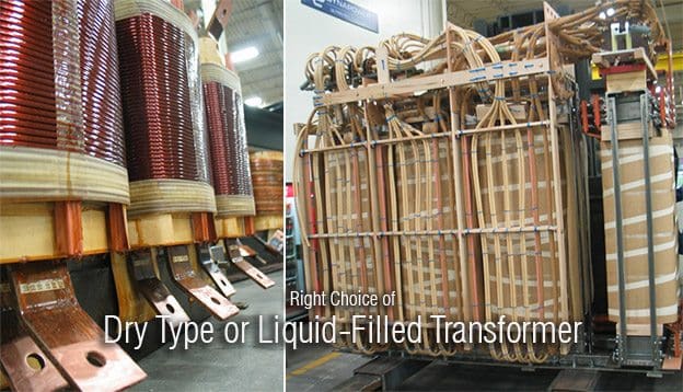
Right Choice of Dry Type or Liquid-Filled Transformer

Right Choice of Dry Type or Liquid-Filled Transformer (on photo Dynapower Corporation transformers)

Content

1. Two Types of Transformers
2. Cooling and insulating system
3. Losses
4. Operating Life of Transformer
5. Maintainability
6. Repairability
7. Core/Coil Reclamation and Recycling
8. Operating Sound Level and Noise Pollution
9. Footprint
0. Conclusion


Two Types of Transformers

Information on the pros and cons of the available types of transformers frequently varies depending upon what information is made available by the manufacturer. Nevertheless, there are certain performance and application characteristics that are almost universally accepted.

Basically, there are two distinct types of transformers: Liquid insulated and cooled (liquid-filled type) and non liquid insulated, air or air/gas cooled (dry type). Also, there are subcategories of each main type.

For liquid-filled transformers, the cooling medium can be conventional mineral oil. There are also wettype transformers using less flammable liquids, such as high fire point hydrocarbons and silicones.

Liquid-filled transformers are normally more efficient than dry-types, and they usually have a longer life expectancy. Also, liquid is a more efficient cooling medium in reducing hot spot temperatures in the coils. In addition, liquid-filled units have a better overload capability.

There are some drawbacks, however.

For example, fire prevention is more important with liquid-type units because of the use of a liquid cooling medium that may catch fire. (Dry-type transformers can catch fire, too.) It’s even possible for an improperly protected wet-type transformer to explode.

And, depending on the application, liquid-filled transformers may require a containment trough for protection against possible leaks of the fluid.

Arguably, when choosing transformers, the changeover point between dry-types and wet-types is between 500kVA to about 2.5MVA, with dry-types used for the lower ratings and wet-types for the higher ratings.

Important factors when choosing what type to use include where the transformer will be installed, such as inside an office building or outside, servicing an industrial load.

Dry-type transformers with ratings exceeding 5MVA are available, but the vast majority of the higher-capacity transformers are liquid-filled. For outdoor applications, wet-type transformers are the predominate choice.

The flowing Table shows losses in dry type and oil filled type transformers:


Table: Comparison of Losses: Oil type and dry type

(Oil Transformer) LossesDry Type Transformer Losses
KVAHalf Load (W)Full Load (W)KVAHalf Load (W)Full Load (W)
50024654930500500010000
75039507900750750015000
1000436087201000820016400
150069401388015001125022500
200081551631020001320026400

Purchases of transformers are often based on the first cost (without any consideration of long-term economics) when transformer evaluation and purchase decisions are not made by the end-user.

This is particularly true when agents or electrical contractors make purchase decisions on the basis of temperature rise and low first cost for commercial and industrial end-users buying dry-type, pad-mounted transformers.

These agents or contractors may have little incentive to take into consideration any economic factors other than the transformer’s first cost. End-user concerns about higher first costs discourage OEMs and contractors from offering or recommending the more expensive, efficient options to customer who do not specifically request them.

Go to Content ↑

Cooling and insulating system

Because air is the basic cooling and insulating system for dry-type transformers, all dry-type transformers will be larger than liquid-immersed units for the same voltage and capacity (kilovolt/kilovolt-ampere) rating.

When operating at the same flux and current density, more material for core and coil implies higher losses and higher costs.

Dry-type high voltage transformer insulation system

Dry-type high voltage transformer insulation system - Glass polyester laminate insulation sheet

These trade-offs are inherent in the design of dry-type units, but dry-type transformers have traditionally offered certain fire-resistant, environmental, and application advantages for industrial and commercial situations.

Recent advances in liquid-filled units are reducing some of these (dry-type) advantages.

When purchased on the basis of lowest first cost, dry type transformers typically have significantly higher operating losses than the more efficient liquid filled transformers.

For this reason the major utilities seldom purchase dry type transformers. Because dry-type insulation systems lack the additional cooling and insulating properties of the oil-paper systems, for the same rating the dry-type transformers tend to be more costly, larger, and have greater losses than a corresponding liquid-immersed unit.

Go to Content ↑


Losses

2500 kVA transformer

2500 kVA transformer

Combined Losses at 100% Loading

Above graphic shows combined losses at 100% loading based on:

Liquid:Cast:Dry:
Load Losses (kW)16.3821.0018.52
No Load Losses (kW)2.667.007.55
Total Losses (kW)19.0426.0728.00

Above values are typical.

Go to Content ↑


50% Loading

At 50% loading, the no-load loss remains the same, and load loss is reduced by the inverse square:

Liquid:Cast:Dry:
Load Losses (kW)4.104.635.25
No Load Losses (kW)2.667.007.55
Total Losses (kW)6.7612.1812.25

Go to Content ↑

Costs Of Transformer Losses

Costs Of Transformer Losses – Transformer Energy Consumption:

Constants:
Energy Costs = $0.06/kWh (Conservative Value)
8760 hours = 24hrs/day * 365 days per year

Liquid:Cast:Dry:
Total Losses (kW)6.7612.1812.25
KWH Billing Rate:x$0.06$0.06$0.06
Annual Hours:x876087608760
Annual Cost of Energy due to
Losses @ 50% Load:

=

$3,553$6,402$6,439
Excess Annual Energy Costs:Base$2,849$2,886
10-Yr* Excess Energy Costs:Base$28,490$28,860

*Simple costs, assumes no interest rate or escalating energy costs

Go to Content ↑


Additional Cost Of Transformer Losses

Additional Cost Of Transformer Losses – Air Conditioning Energy Consumption:

Energy consumption by the transformer is not the only energy factor. Transformer losses are dissipated as heat, which must be removed from a controlled temperature environment by air conditioning.

Illustrated below are calculations to convert transformer losses into increased air conditioning energy consumption.

Constants:
1kW = 3415BTU/Hr
1Ton Air Conditioning = 12000BTU/Hour
1Ton Air Conditioning = 1.7kW power use

Liquid:Cast:Dry:
Total Losses (kW)6.7612.1812.25
BTU/HR/KW:x341534153415
BTU/HR:=230854159541834
BTU/HR per ton A/C:

÷

120001200012000
A/C (tons): =1.923.473.49
kW power usage per ton A/C: x1.71.71.7
kW:=3.275.895.93
Annual Hours of Operation (h):x876087608760
Annual energy usage (kWh):=286495161951916
kWH billing rate:x$0.06$0.06$0.06
Annual Cooling Costs:=$1,718.94$3,097$3,115
Excess Annual Cooling Costs:base$1,378$1,396
10-Yr Excess Energy Costs:base$13,782$13,960

Go to Content ↑

Operating Life of Transformer

Typical dry-type lifespan: 15-25 Years
Typical liquid-filled lifespan: 25-35 Years

The retirement age of transformers removed from service for a variety of reasons ranges from 14 to 35 years; the average is 25 years. However, the average life of liquidimmersed transformers that remain in service is 30 years or more.

Because liquid-filled transformers last longer than dry-type, they save on material, labor to replace, and operational impact due to outage to replace.

Go to Content ↑


Maintainability

Recommended annual maintenance for a typical dry-type transformer consists of inspection, infrared examination of bolted connections, and vacuuming of grills and coils to maintain adequate cooling and prevent buildup of flammable material.

Cleaning of the grill and coils may require the undesirable requirement of de-energizing the transformer, often leading to no cleaning. Omitting the cleaning decreases the transformer efficiency due to decreased airflow and creates a fire hazard.

Preventive maintenance for a liquid-filled transformer may consist of drawing and analyzing an oil sample. The oil analysis provides a very accurate assessment of the transformer condition – something not possible with dry-type transformers. Omitting the preventive maintenance does not decrease transformer efficiency or create a potential fire hazard.

Less-flammable liquid-filled transformers provide the best opportunity to enable maximum efficiency with the least maintenance, and provide the best diagnostics for repair/re-use rather than unforeseen failure/disposal.

Go to Content ↑


Repairability

“Coils in liquid-type units are much easier to repair than coils in dry-type transformers. Cast coils are not repairable; they must be replaced.” – Moran, Robert B. Guidelines for transformer application designs. Electrical Construction and Maintenance, May 1996.

When a transformer fails, a decision to repair or replace the transformer must be made. Liquid-filled transformers, in most situations, can be economically repaired at local independent service repair facilities.

Liquid-filled transformers provide the best opportunity to repair existing equipment rather than dispose and replace.

Example: 2500kVA Transformer – Purchase and Maintenance

LiquidCastDry
Purchase Price:$35,000$60,000$38,000
Operating Life (years):353025
Annual Maintenance:none6 hours6 hours
Annual Maintenance:none$360$360
Outage Required for Maintenance:N/AYesYes
Fire Hazard if not Maintained:NoYesYes
Repairable:YesNoYes
Annual cost to purchase and maintain:$902$1,693$1,376

Go to Content ↑

Core/Coil Reclamation and Recycling

Feature: Liquid filled transformers allow easier core/coil reclamation
Materials & Resources Benefit: Easier to recycle

Utility companies who use most of the liquid-filled transformers typically replace the coils on old transformers and continue to use them for a large percentage of their old substation transformers. The small distribution transformers are disposed/recycled when they reach an end of life.

When it comes time to decommission a transformer, recycling offsets the need for new material and provides a positive cash flow. Most components of liquid-filled and dry-type transformers can be recycled. Cast resin type transformers are an exception. Because of their construction, the materials in cast resin type transformers can be difficult and uneconomical to recycle. When a cast coil fails, the entire winding, encapsulated in epoxy resin, is rendered useless and typically ends up in a landfill.

This wastes the resource and creates additional costs for disposal, plus long-term liability exposure to the original owner.

In contrast, liquid-filled transformers can be easily recycled after their useful life. The transformer fluid can be reconditioned and used again, and the steel, copper, and aluminum can be completely and economically recycled, providing a positive cash flow.

The scrap values and disposal costs for a 2500 kVA transformer are shown below. Positive cash flows are shown in parentheses.

2500kVA Transformer

Dry TypeCast ResinLiquid Filled
Dielectric Fluid$0$0$500
Core and Coil$1100$100$1200
Tank and Fitting$400$100$400
Disposal Costs$0$400$0
Total Costs (or Savings)$1500$200$2100

Operating Sound Level and Noise Pollution

Feature: Liquid filled transformers have a lower operating sound level
Indoor Environmental Quality Benefit: Less noise pollution

Transformer types comparison - Operating sound level

Transformer types comparison - Operating sound level


Decibels is a logarithmic function, and sound pressure doubles for every three decibel  increase. Research shows that decibel levels over 60 can reduce a person’s attention  span.

A study by the American Society of Interior Designers showed that office  productivity would increase if workspaces were less noisy.

Go to Content ↑


Footprint

Feature: Liquid filled transformers have a smaller footprint
Materials and Resources Benefit: Smaller equipment reduces building size demand

Constants:
Typical cost per square foot: $25/SF

kVALiquid:Dry:Difference: $25/SF:
750kVADepth:4.6 ft5.5 ft
Width:4.6 ft8.0 ft
Sq Ft:21 ft244 ft223 ft2$575
1000kVADepth:5.2 ft5.5 ft
Width:4.8 ft8.0 ft
Sq Ft:25 ft244 ft219 ft2$475
1500kVADepth:6.3 ft5.5 ft
Width:4.4 ft8.0 ft
Sq Ft:28 ft244 ft216 ft2$400

A smaller building also has the benefit of requiring less lighting and ventilation.

Go to Content ↑

Conclusion

Use of liquid-filled transformer(s) for commercial and industrial facilities is an innovative design practice. A dry-type transformer is the standard solution for providing power in this type of design.

A total owning cost evaluation of both dry-type and liquid-filled transformers will show the lowest total owning cost choice is the installation of less-flammable liquid filled transformers.

Go to Content ↑

Resources: Best Practice Manual for transformers - Devki Energy Consultancy Pvt. Ltd.; Application for LEED Innovation & Design Points - Transformer Technology:  Liquid-Filled vs. Dry-Type

Designing of HV Power Substation and Layout

$
0
0
Designing of High Voltage Power Substation and Layout

Designing of High Voltage Power Substation and Layout (photo by Noritaka Tasho @ Flickr)

Content

  1. Introduction
  2. Earthing and Bonding
  3. Substation Earthing Calculation Methodology (Earthing Materials)
  4. Layout of Substation
  5. Different Layouts for Substations (single busbar, mesh, 1 1/2 cb)
  6. Principle of Substation Layouts (spatial separation, maintenance zones)
  7. Components of a Substation (cbs, cts, isolators, insulation, transformers etc.)

Introduction

Substations are the points in the power network where transmission lines and distribution feeders are connected together through circuit breakers or switches via busbars and transformers. This allows for the control of power flows in the network and general switching operations for maintenance purposes.

The first step in designing a power substation is to design an earthing and bonding system.

Go to Content ↑


Earthing and Bonding

The function of an earthing and bonding system is to provide an earthing system connection to which transformer neutrals or earthing impedances may be connected in order to pass the maximum fault current. The earthing system also ensures that no thermal or mechanical damage occurs on the equipment within the power substation, thereby resulting in safety too peration and maintenance personnel.

The earthing system also guarantees equipotential bonding such that there are no dangerous potential gradients developed in the substation.

In designing the substation, three voltage have to be considered:
  1. Touch Voltage: This is the difference in potential between the surf ace potential and the potential at an Earthed equipment whilst a man is standing and touching the earthed structure.
  2. Step Voltage: This is the potential difference developed when a man bridges a distance of 1m with his Feet while not touching any other earthed equipment.
  3. Mesh Voltage: This is the maximum touch voltage that is developed inthe mesh of the earthing grid.

Go to Content ↑


Substation Earthing Calculation Methodology

Calculations for earth impedances and touch and step potentials are based on site measurements of ground resistivity and system fault levels. A grid layout with particular conductors is then analyzed to determine the effective substation earthing resistance, from which the earthing voltage is calculated. In practice, it is normal to take the highest fault level for substation earth grid calculation purposes.

Additionally, it is necessary to ensure a sufficient margin such that expansion of the system is catered for.

To determine the earth resistivity, probe tests are carried out on the site. These tests are best performed in dry weather such that conservative resistivity readings are obtained.


Earthing Materials

1. Conductors

Bare copper conductor is usually used for the substation earthing grid. The copper bars Themselves usually have a cross-sectional area of 95 square millimeters, and they are laid at a shallow Depth of 0.25-0.5m, in 3-7m squares.

In addition to the buried potential earth grid, a separate above ground earthing ring is usually provided, to which all metallic substation plant is bonded.

2. Connections:

Connections to the grid and other earthing joints should not be soldered because the heat generated during fault conditions could cause a soldered joint to fail. Joints are usually bolted and in this case, the face of the joints should be tinned.

3. Earthing Rods

The earthing grid must be supplemented by earthing rods to assist in the dissipation of earth fault currents and further reduce the overall substation earthing resistance. These rods are usually made of solid copper, or copper clad steel.

4. Switchyard Fence

Earthing: The switchyard fence earthing practices are possibleand are used by different utilities.

These are:

  1. Extend the substation earth grid 0.5m-1.5m beyond the fence perimeter. The fence is then bonded to the grid at regular intervals.
  2. Place the fence beyond the perimeter of the switchyard earthing grid and bond the fence to its own earthing rod system. This earthing rod system is not coupled to the main substation earthing grid.

Go to Content ↑


Layout of Substation

The layout of the substation is very important since there should be a security of supply.

In an ideal substation all circuits and equipment would be duplicated such that following a fault, or during maintenance, a connection remains available. Practically this is not feasible since the cost of implementing such a design is very high.

Methods have been adopted to achieve a compromise between complete security of supply and capital investment.

There are four categories of substation that give varying securities of supply:

  • Category 1 - No outage is necessary within the substation for either maintenance or fault conditions.
  • Category 2 - Short outage is necessary to transfer the load to an alternative circuit for maintenance or fault conditions.
  • Category 3 - Loss of a circuit or section of the substation due to fault or maintenance.
  • Category 4 - Loss of the entire substation due to fault or maintenance.

Go to Content ↑


Different Layouts for Substations

Single Busbar

The general schematic for such a substation is shown in the figure below.

Single- busbar substation layout

Single- busbar substation layout


With this design, there is an ease of operation of the substation. This design also places minimum reliance on signalling for satisfactory operation of protection. Additionally there is the facility to support the economical operation of future feeder bays.

Such a substation has the following characteristics:

  1. Each circuit is protected by its own circuit breaker and hence plant outage does not necessarily result in loss of supply.
  2. A fault on the feeder or transformer circuit breaker causes loss of the transformer and feeder circuit, one of which may be restored after isolating the faulty circuit breaker.
  3. A fault on the bus section circuit breaker causes complete shutdown of the substation. All circuits may be restored after isolating the faulty circuit breaker. A busbar fault causes loss of one transformer and one feeder.
  4. Maintenance of one busbar section or isolator will cause the temporary outage of two circuits.
  5. Maintenance of a feeder or transformer circuit breaker involves loss of the circuit.
  6. Introduction of bypass isolators between busbar and circuit isolator allows circuit breaker maintenance facilities without loss of that circuit.

Go to Content ↑


Mesh Substation

The general layout for a full mesh substation is shown in the schematic below.

Full mesh substation layout

Full mesh substation layout


The characteristics of such a substation are as follows. Operation of two circuit breakers is required to connect or disconnect a circuit, and disconnection involves opening of a mesh. Circuit breakers may be maintained without loss of supply or protection, and no additional bypass facilities are required.

Busbar faults will only cause the loss of one circuit breaker. Breaker faults will involve the loss of a maximum of two circuits. generally, not more than twice as many outgoing circuits as in feeds are used in order to rationalize circuit equipment load capabilities and ratings.

Go to Content ↑


One and a half Circuit Breaker layout

The layout of a 1 1/2 circuit breaker substation is shown in the schematic below.

One and a half Circuit Breaker layout

One and a half Circuit Breaker layout


The reason that such a layout is known as a 1 1/2 circuit breaker is due to the fact that in the design, there are 9 circuit breakers that are used to protect the 6 feeders. Thus, 1 1/2 circuit breakers protect 1 feeder.

Some characteristics of this design are:

  1. There is the additional cost of the circuit breakers together with the complex arrangement.
  2. It is possible to operate any one pair of circuits, or groups of pairs of circuits.
  3. There is a very high security against the loss of supply.

Go to Content ↑


Principle of Substation Layouts

Substation layout consists essentially in arranging a number of switchgear components in an ordered pattern governed by their function and rules of spatial separation.


Spatial Separation

  1. Earth Clearance - this is the clearance between live parts and earthed structures, walls, screens and ground.
  2. Phase Clearanc - this is the clearance between live parts of different phases.
  3. Isolating Distance - this is the clearance between the terminals of an isolator and the connections There to.
  4. Section Clearance - this is the clearance between live parts and the terminals of a work section. The limits of this work section, or maintenance zone, may be the ground or a platform from which the man works.

Go to Content ↑


Separation of Maintenance Zones

Two methods are available for separating equipment in a maintenance zone that has been isolated and made dead:

  1. The provision of a section clearance
  2. Use of an intervening earthed barrier

The choice between the two methods depends on the voltage and whether horizontal or vertical clearances are involved. A section clearance is composed of a the reach of a man, taken as 8 feet, plus an earth clearance. For the voltage at which the earth clearance is 8 feet, the space required will be the same whether a section clearance or an earthed barrier is used.

HENCE:

Separation by earthed barrier = Earth Clearance + 50mm for barrier + Earth Clearance
Separation by section clearance = 2.44m + Earth clearance

For vertical clearances it is necessary to take into account the space occupied by the equipment and the need for an access platform at higher voltages. The height of the platform is taken as 1.37m below the highest point of work.

Go to Content ↑


Establishing Maintenance Zones

Some maintenance zones are easily defined and the need for them is self evident as is the case of a circuit breaker. There should be a means of isolation on each side of the circuit breaker, and to separate it from adjacent live parts, when isolated, either by section clearances or earth barriers.

Go to Content ↑


Electrical Separations

Together with maintenance zoning, the separation, by isolating distance and phase clearances, of the substation components and of the conductors interconnecting them constitute the main basis of substation layouts.

There are at least three such electrical separations per phase that are needed in a circuit:

  1. Between the terminals of the bus bar isolator and their connections.
  2. Between the terminals of the circuit breaker and their connections.
  3. Between the terminals of the feeder isolator and their connections.

Go to Content ↑


Components of a Substation

The substation components will only be considered to the extent where they influence substation layout.


Circuit Breakers

There are two forms of open circuit breakers:

  1. Dead Tank – circuit breaker compartment is at earth potential.
  2. Live Tank – circuit breaker compartment is at line potential.

The form of circuit breaker influences the way in which the circuit breaker is accommodated. This may be one of four ways.

1. Ground Mounting and Plinth Mounting

The main advantages of this type of mounting are its simplicity, ease of erection, ease of maintenance and elimination of support structures. An added advantage is that in indoor substations, there is the reduction in the height of the building. A disadvantage however is that to prevent danger to personnel, the circuit breaker has to be surrounded by an earthed barrier, which increases the area required.

Retractable Circuit Breakers

These have the advantage of being space saving due to the fact that isolators can be accommodated in the same area of clearance that has to be allowed between the retractable circuit breaker and the live fixed contacts. Another advantage is that there is the ease and safety of maintenance. Additionally such a mounting is economical since at least two insulators per phase are still needed to support the fixed circuit breaker plug contacts.

Suspended Circuit Breakers

At higher voltages tension insulators are cheaper than post or pedestal insulators. With this type of mounting the live tank circuit breaker is suspended by tension insulators from overhead structures, and held in a stable position by similar insulators tensioned to the ground. There is the claimed advantage of reduced costs and simplified foundations, and the structures used to suspend the circuit breakers may be used for other purposes.

Go to Content ↑


Current Transformers

CT’s may be accommodated in one of six manners:

  1. Over Circuit Breaker bushings or in pedestals.
  2. In separate post type housings.
  3. Over moving bushings of some types of insulators.
  4. Over power transformers of reactor bushings.
  5. Over wall or roof bushings.
  6. Over cables.

In all except the second of the list, the CT’s occupy incidental space and do not affect the size of the layout. The CT’s become more remote from the circuit breaker in the order listed above. Accommodation of CT’s over isolator bushings, or bushings through walls or roofs, is usually confined to indoor substations.

Go to Content ↑


Isolators

These are essentially off load devices although they are capable of dealing with small charging currents of busbars and connections. The design of isolators is closely related to the design of substations.

Isolator design is considered in the following aspects:

  • Space Factor
  • Insulation Security
  • Standardisation
  • Ease of Maintenance
  • Cost

Some types of isolators include:

  • Horizontal Isolation types
  • Vertical Isolation types
  • Moving Bushing types

Go to Content ↑


Conductor Systems

An ideal conductor should fulfil the following requirements:

  • Should be capable of carrying the specified load currents and short time currents.
  • Should be able to withstand forces on it due to its situation. These forces comprise self weight, and
  • Weight of other conductors and equipment, short circuit forces and atmospheric forces such as wind and ice loading.
  • Should be corona free at rated voltage.
  • Should have the minimum number of joints.
  • Should need the minimum number of supporting insulators.
  • Should be economical.

The most suitable material for the conductor system is copper or aluminium. Steel may be used but has limitations of poor conductivity and high susceptibility to corrosion. In an effort to make the conductor ideal, three different types have been utilized, and these include:

  • Flat surfaced Conductors
  • Stranded Conductors
  • Tubular Conductors

Go to Content ↑


Insulation

Insulation security has been rated very highly among the aims of good substation design.

Extensive research is done on improving flashover characteristics as well as combating pollution. Increased creepage length, resistance glazing, insulation greasing and line washing have been used with varying degrees of success.

Go to Content ↑


Power Transformers

EHV power transformers are usually oil immersed with all three phases in one tank. Auto transformers can offer advantage of smaller physical size and reduced losses.

The different classes of power transformers are:

  • o.n.: Oil immersed, natural cooling
  • o.b.: Oil immersed, air blast cooling
  • o.f.n.: Oil immersed, oil circulation forced
  • o.f.b.: Oil immersed, oil circulation forced, air blast cooling

Power transformers are usually the largest single item in a substation. For economy of service roads, transformers are located on one side of a substation, and the connection to switchgear is by bare conductors. Because of the large quantity of oil, it is essential to take precaution against the spread of fire.

Hence, the transformer is usually located around a sump used to collect the excess oil. Transformers that are located and a cell should be enclosed in a blast proof room.

Go to Content ↑


Overhead Line Terminations

Two methods are used to terminate overhead lines at a substation.

  1. Tensioning conductors to substation structures or buildings
  2. Tensioning conductors to ground winches.

The choice is influenced by the height of towers and the proximity to the substation. The following clearances should be observed:

Voltage LevelMinimum Ground Clearance
Less than 66kV6.1 m
66kV – 110kV6.4 m
110kV – 165kV6.7 m
Greater than 165kV7.0 m

Go to Content ↑

Resource: Mr Alvin Lutchman, Lecturer at University of West Indies

Definitions of Abnormal Voltage Conditions

$
0
0
Definitions of Abnormal Voltage Conditions

Definitions of Abnormal Voltage Conditions (Sag, Swell, Surge and Interruption)

Sag

A sag is a temporary reduction in the normal AC voltage.

A momentary sag is a variation, which lasts for a period of 0.5 cycle to about 2 s usually the result of a short circuit somewhere in the power system. Instances of longer duration of low voltage are called sustained sags (see Figure 1).

Sag - momentary and sustained

Figure 1 - Sag - momentary and sustained

Swell

Swell is the opposite of sag and refers to the increase of power frequency voltage. A momentary swell lasts from 0.5 cycles to 2 s. A sustained swell lasts for longer periods (see Figure 2).

Swell - momentary and sustained

Figure 2 - Swell - momentary and sustained

Surge

Surge is a sub-cycle disturbance lasting for a duration of less than half a cycle and mostly less than a millisecond. The earlier terminology was transient or spikes.

The decay is usually oscillatory. Surges generally occur due to atmospheric disturbances such as lightning or due to switching of large transformers, inductors or capacitors (see Figures 3a and b for examples).

Surge voltage with oscillatory decay

Figure 3a - Surge voltage with oscillatory decay


Surge caused by lightning

Figure 3b - Surge caused by lightning

Interruption

Interruption means the complete loss of voltage. A momentary interruption lasts from half-cycle period to less than 2 s. Longer interruptions are called sustained interruption.

Momentary interruption is usually the result of a line outage with the supply being restored automatically from another source or by auto-reclosing operation. Refer Figure 4 for illustration. An interruption can be instantaneous or of slowly decaying type.

Examples of supply interruption

Figure 4 - Examples of supply interruption


In Figure 4, the one at the top shows the RMS voltage value during a momentary interruption. The figure on the lower left depicts the waveform of a sustained interruption where the voltage drops to zero almost instantaneously.

The waveform on the lower right shows an interruption where the voltage decays slowly.

Resource: Grounding-Bonding-Shielding-and-Surge-Protection – G. Vijayaraghavan, B.Eng (Hons) Consulting Engineer, Chennai, India

Dry Transformer Percent Impedance Definition

$
0
0
Dry Transformer Percent Impedance Definition

Dry Transformer Percent Impedance Definition (on photo dry type transformer by Engineering company B&S, Ukraine)

Introduction

The percent impedance is the percent voltage required to circulate rated current flow through one transformer winding when another winding is short-circuited at the rated voltage tap at rated frequency.

%Z is related to the short circuit capacity of the transformer during short circuit conditions.

For a two winding transformer with a 5% impedance, it would require 5% input voltage applied on the high voltage winding to draw 100% rated current on the secondary winding when the secondary winding is short-circuited.

If 100% rated voltage is applied to the high voltage winding, approximately 20X rated current would flow in the secondary winding when the secondary winding is short-circuited.


Impedance Levels

Based kVAMinimum Impedance, %
0 – 150Manufacturer’s standard
151 – 3004
301 – 6005
601 – 2,5006
2,501 – 5,0006.5
5,001 – 7,5007.5
7,501 – 10,0008.5
Above 10,0009.5

Important Notes

  1. The impedance of a two-winding transformer shall not vary from the guaranteed value by more that ± 7.5%
  2. The impedance of a transformer having three or more windings or having zig-zag windings shall not vary from the guaranteed value by more than ± 10%
  3. The impedance of an auto-transformer shall not vary from the guaranteed value by more than ± 10%
  4. The difference of impedances between transformers of the same design shall not exceed 10% of the guaranteed values
  5. Differences of impedance between auto-transformers of the same design shall not exceed 10% of the guaranteed values

Impedance vs. Percent Impedance

Impedance is defined, in the Standard Handbook for Electrical Engineers, as “the apparent resistance of an alternating current circuit or path… the vector sum of the resistance and reactance of the path”. Impedance may be comprised of resistance, capacitive reactance and inductive reactance, and is expressed in ohms.

From the perspective of a load, the total input impedance may include the impedance of the upstream generator, transformer, line reactor and conductors.

The power system impedance is useful for estimating the available short circuit current.

Sample calculations for a three phase transformer rated 500kVA, 4160:480, 60Hz, 6% impedance:
Transformer reactance Xt = (kV2/MVA) x %Z/100 = (0.482 / 0.5) x 0.06 = 0.027648 ohms
Approximate available short circuit current = 480/(1.732 x 0.027648) = 10,023.7 amps


Effective Percent Impedance

Effective impedance is the relative impedance of a reactor or transformer under actual operating conditions. Since smaller (kVA) loads have higher impedance and thus draw lower current than larger (kVA) loads, the internal ohms of a reactor or transformer represent a smaller percentage of the load impedance for a small (kVA) load than for a large load.

The value in ohms will cause a lower voltage drop when less than rated reactor or transformer current is flowing. If the load is only one half the rated current, then the voltage drop across the impedance will be onehalf of the rated voltage drop.

Sample calculations for a three phase transformer rated 500kVA, 4160:480, 60Hz, 6% impedance:

Transformer reactance Xt = (kV2/MVA) x %Z/100 = (0.482 / 0.5) x 0.06 = 0.027648 ohms
Rated secondary current = 500,000 / (480 x 1.732) = 601.4 amps
Actual Load current = 300 amps
Voltage drop at actual load = 300 x 1.732 x 0.027648 = 14.36 volts (14.36 / 480 = 0.0299, or 3% of 480 volts)
Effective percent impedance = 6% x (300 / 601.4) = 2.99%


Transformer Percentage Impedance (VIDEO)

Cant see this video? Click here to watch it on Youtube.

Resource: Substation Comissioning Course – Dry Type Transformer

Basic Steps In PLC Programming

$
0
0
Basic Steps In PLC Programming

Basic Steps In PLC Programming (photo by ProWest Engineering)


The first step in developing a control program is the definition of the control task. The control task specifies what needs to be done and is defined by those who are involved in the operation of the machine or process. The second step in control program development is to determine a control strategy, the sequence of processing steps that must occur within a program to produce the desired output control.

This is also known as the development of an algorithm.

A set of guidelines should be followed during program organization and implementation in order to develop an organized system.

Approach guidelines apply to two major types of projects: new applications and modernizations of existing equipment.

Flow charting can be used to plan a program after a written description has been developed. A flowchart is a pictorial representation of the process that records, analyzes, and communicates information, as well as defines the sequence of the process.

Logic gates or contact symbology are used to implement the logic sequences in a control program. Inputs and outputs marked with an “X” on a logic gate diagram represent real I/O.

Three important documents that provide information about the arrangement of the PLC system are the I/O assignment table, the internal address assignment table, and the register address assignment table.
  1. The I/O assignment table documents the names, locations, and descriptions of the real inputs and outputs.
  2. The internal address assignment table records the locations and descriptions of internal outputs, registers, timers, counters, and MCRs.
  3. The register address assignment tablelists all of the available PLC registers.

Certain parts of the system should be left hardwired for safety reasons. Elements such as emergency stops and master start push buttons should be left hardwired so that the system can be disabled without PLC intervention.

Special cases of input device programming include the program translation of normally closed input devices, fenced MCR circuits, circuits that allow bidirectional power flow, instantaneous timer contacts, and complicated logic rungs.

  • The programming of contacts as normally open or normally closed depends on how they are required to operate in the logic program. In most cases, if a normally closed input device is required to act as a normally closed input, its reference address is programmed as normally open.
  • Master control relays turn ON and OFF power to certain logic rungs. In a PLC program, an END MCR instruction must be placed after the last rung an MCR will control.
  • PLCs do not allow bidirectional power flow, so all PLC rungs must be programmed to operate only in a forward path.
  • PLCs do not provide instantaneous contacts; therefore, an internal output must be used to trap a timer that requires these contacts.
  • Complicated logic rungs should be isolated from the other rungs during programming.
Program coding is the process of translating a logic or relay diagram into PLC ladder program form.

The benefits of modernizing a relay control system include greater reliability, less energy consumption, less space utilization, and greater flexibility.


Example Of Simple Start/Stop Motor Circuit

Figure 1 shows the wiring diagram for a three-phase motor and its corresponding three-wire control circuit, where the auxiliary contacts of the starter seal the start push button. To convert this circuit into a PLC program, first determine which control devices will be part of the PLC I/O system; these are the circled items in Figure 2. In this circuit, the start and stop push buttons (inputs) and the starter coil (output) will be part of the PLC system.

The starter coil’s auxiliary contacts will not be part of the system because an internal will be used to seal the coil, resulting in less wiring and fewer connections.

Wiring diagram of three phase motor

Figure 1a - Wiring diagram of three phase motor


Relay control circuit for a three-phase motor

Figure 1b - Relay control circuit for a three-phase motor


Real inputs and outputs to the PLC

Figure 2 - Real inputs and outputs to the PLC

Table 1 shows the I/O address assignment, which uses the same addressing scheme as the circuit diagram (i.e., inputs: addresses 000 and 001, output: address 030).

I/O Address
Module TypeRackGroupTerminalDescription
Input000Stop PB (NC)
001Start PB
002-
003-
Output030Motor M1
031-
032-
033-

To program the PLC, the devices must be programmed in the same logic sequence as they are in the hardwired circuit (see Figure 3). Therefore, the stop push button will be programmed as an examine-ON instruction (a normally open PLC contact) in series with the start push button, which is also programmed as an examine-ON instruction.

This circuit will drive output 030, which controls the starter.

PLC implementation of the circuit in Figure 1

Figure 3 - PLC implementation of the circuit in Figure 1


If the start push button is pressed, output 030 will turn ON, sealing the start push button and turning the motor ON through the starter. If the stop push button is pressed, the motor will turn OFF.

Note that the stop push button is wired as normally closed to the input module. Also, the starter coil’s overloads are wired in series with the coil.

Resource: Introduction to PLC Programming and Implementation—from relay logic to PLC logic


How to Protect Capacitor Banks?

$
0
0
How to Protect Capacitor Banks?

How to Protect Capacitor Banks?

Introduction

Capacitor banks are used to compensate for reactive energy absorbed by electrical system loads, and sometimes to make up filters to reduce harmonic voltage.

Their role is to improve the quality of the electrical system. They may be connected in star, delta and double star arrangements, depending on the level of voltage and the system load.

A capacitor comes in the form of a case with insulating terminals on top. It comprises individual capacitances which have limited maximum permissible voltages (e.g. 2250 V) and are series-mounted in groups to obtain the required voltage withstand and parallel-mounted to obtained the desired power rating.

Capacitor bank

Capacitor bank


There are two types of capacitors:

  1. Those with no internal protection,
  2. Those with internal protection: a fuse is combined with each individual capacitance.

Types of faults

The main faults which are liable to affect capacitor banks are:

  1. Overload,
  2. Short-circuit,
  3. Frame fault,
  4. Capacitor component short-circuit

1. Overload

An overload is due to temporary or continuous overcurrent:

Continuous overcurrent linked to:

  • Raising of the power supply voltage,
  • The flow of harmonic current due to the presence of non-linear loads such as static converters (rectifiers, variable speed drives), arc furnaces, etc.,

Temporary overcurrent linked to the energizing of a capacitor bank step. Overloads result in overheating which has an adverse effect on dielectric withstand and leads to premature capacitor aging.


2. Short Circuit

A short-circuitis an internal or external fault between live conductors, phase-to-phase or phase-to-neutral depending on whether the capacitors are delta or star-connected.

The appearance of gas in the gas-tight chamber of the capacitor creates overpressure which may lead to the opening of the case and leakage of the dielectric.


3. Frame fault

A frame fault is an internal fault between a live capacitor component and the frame created by the metal chamber.

Similar to internal short-circuits, the appearance of gas in the gas-tight chamber of the capacitor creates overpressure which may lead to the opening of the case and leakage of the dielectric.


4. Capacitor component short-circuit

A capacitor component short-circuit is due to the flashover of an individual capacitance.

With no internal protection: The parallel-wired individual capacitances are shunted by the faulty unit:

  • The capacitor impedance is modified
  • The applied voltage is distributed to one less group in the series
  • Each group is submitted to greater stress, which may result in further, cascading flashovers, up to a full short-circuit.

With internal protection: the melting of the related internal fuse eliminates the faulty individual capacitance: the capacitor remains fault-free, its impedance is modified accordingly.

Protection devices

Capacitors should not be energized unless they have been discharged. Re-energizing must be time-delayed in order to avoid transient overvoltage. A 10-minute time delay allows sufficient natural discharging.

Fast discharging reactors may be used to reduce discharging time.


Overloads

Overcurrent of long duration due to the raising of the power supply voltage may be avoided by overvoltage protection that monitors the electrical system voltage. This type of protection may be assigned to the capacitor itself, but it is generally a type of overall electrical system protection.

Given that the capacitor can generally accommodate a voltage of 110% of its rated voltage for 12 hours a day, this type of protection is not always necessary.
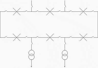
Overcurrent of long duration due to the flow of harmonic current is detected by an overload protection of one the following types:
  • Thermal overload
  • Time-delayed overcurrent

provided it takes harmonic frequencies into account.

The amplitude of overcurrent of short duration due to the energizing of capacitor bank steps is limited by series-mounting impulse reactors with each step.


Short circuits

Short-circuits are detected by a time-delayed overcurrent protection device. Current and time delay settings make it possible to operate with the maximum permissible load current and to close and switch steps.


Frame faults

Protection depends on the grounding system. If the neutral is grounded, a time-delayed earth fault protection device is used.

Capacitor component short-circuits: Detection is based on the change in impedance created by the short-circuiting of the component for capacitors with no internal protection by the elimination of the faulty individual capacitance for capacitors with internal fuses.

When the capacitor bank is double star-connected, the unbalance created by the change in impedance in one of the stars causes current to flow in the connection between the netural points. This unbalance is detected by a sensitive overcurrent protection device.

Examples of capacitor bank protection

Double star connected capacitor bank for reactive power compensation

Double star connected capacitor bank

Double star connected capacitor bank for reactive power compensation


Filter

Filter

Filter

Setting information

Type of faultSetting
OverloadOvervoltage setting: ≤110% Vn
Thermal overload:
setting ≤1.3 In or overcurrent
setting ≤1.3 In direct time
or IDMT time delay 10 sec
Short-circuitOvercurrent direct time setting:
approximately 10 In time delay approximately 0.1 sec
Frame faultEarth fault direct time setting:
≤20% maximum earth fault current
and ≥10% CT rating if suppied by 3 CTs time delay approximately 0.1 sec
Capacitor component short circuitOvercurrent direct time setting:
< 1 ampere time delay approximately 1 sec

Resource: Protection Guide – Schneider Electric

Disturbances In LV Networks Due To Surges

$
0
0
Disturbances Due To Surges

Disturbances Due To Surges

Introduction

There are two types of surge: those generated by a lightning impact and those resulting from electrical switchgear switching operations.


Surges resulting from lightning strokes

Surges resulting from lightning strokes (see figure below) can affect all electrical installations. Consequently, they are without doubt the main source of nuisance tripping of electrical protection devices.

In most cases an earth leakage protection device will trip. The incomer circuit-breaker, if it is of the residual current kind, is the first concerned as it affects the entire electrical installation. Should lightning fall on a line or an electrical installation, it will cause a potential build-up that will lead to arcing to the earth resulting in tripping of earth leakage and/or thermal magnetic protection devices.


Operating Overvoltage

Operating overvoltage (see figure below) result from opening or closing of switchgear on the electrical network (current switching on a high power network).

The phenomenon that creates most disturbance is that generated by surges occurring on the network when a protection device cuts an electric current. The electrical power transmitted by this second surge category is markedly less energetic than that transmitted by a lightning stroke occurring close-by.

Left: Lightning surge; Right: Operating overvoltage

Left: Lightning surge; Right: Operating overvoltage

Surges resulting from breaking of the neutral conductor

In three-phase systems, breaking of the earthed neutral conductor connection results in a potential rise of the neutral (according to load unbalance).

Phase-to-neutral voltage is also affected and can increase by 70% (U0√3).

Displacement of the neutral point in event of breaking

Displacement of the neutral point in event of breaking (case Z1 >> Z2 and Z3)

Home Surge Protection (VIDEO)

Cant see this video? Click here to watch it on Youtube.

Resource: Schneider Electric – Increasing availability of LV electrical networks

Overcurrent Protection of Transformer (NEC 450.3)

$
0
0
Overcurrent Protection of Transformer (NEC 450.3)

Overcurrent Protection of Transformer (NEC 450.3) - Photo by Efrem Oshinsky @ Flickr

Content

  1. Unsupervised location of transformer (impedance <6%)
  2. Unsupervised location of transformer (impedance 6% to 10%)
  3. Supervised location (in primary side only) of transformer
  4. Supervised location of transformer (impedance up to 6%)
  5. Supervised location of transformer (impedance 6% to 10%)
  6. Difference in C.B between supervised & unsupervised Location
  7. Sumary of overcurrent protection for more than 600V
  • Overcurrent Protection of Transformers <600V (NEC 450.3B)
    1. Only primary side protection of transformer
    2. Primary and secondary side protection of transformer
    3. Summary of overcurrent protection for less than 600V

    Introduction

    The overcurrent protection required for transformers is consider for Protection of Transformer only. Such overcurrent protection will not necessarily protect the primary or secondary conductors or equipment connected on the secondary side of the transformer.

    When voltage is switched on to energize a transformer, the transformer core normally saturates.

    This results in a large inrush current which is greatest during the first half cycle (approximately 0.01 second) and becomes progressively less severe over the next several cycles (approximately 1 second) until the transformer reaches its normal magnetizing current. To accommodate this inrush current, fuses are often selected which have time-current withstand values of at least 12 times transformer primary rated current for 0.1 second and 25 times for 0.01 second. Some small dry-type transformers may have substantially greater inrush currents.

    To avoid using over sized conductors, overcurrent devices should be selected at about 110 to 125 percent of the transformer full-load current rating. And when using such smaller overcurrent protection, devices should be of the time-delay type (on the primary side) to compensate for inrush currents which reach 8 to 10 times the full-load primary current of the transformer for about 0.1 s when energized initially.

    Protection of secondary conductors has to be provided completely separately from any primary-side protection.

    A supervised location is a location where conditions of maintenance and supervision ensure that only qualified persons will monitor and service the transformer installation. Overcurrent protection for a transformer on the primary side is typically a circuit breaker. In some instances where there is not a high voltage panel, there is a fused disconnect instead.

    It is important to note that the overcurrent device on the primary side must be sized based on the transformer KVA rating and not sized based on the secondary load to the transformer.

    Go to Content ↑


    Overcurrent Protection of Transformers >600V (NEC450.3A)

    1) Unsupervised Location of Transformer (Impedance <6%)

    Unsupervised Location of Transformer (Impedance <6%)

    Unsupervised Location of Transformer (Impedance <6%)


    • OverCurrent Protection at Primary Side (Primary Voltage >600V):
    • Rating of Pri. Fuse at Point A= 300% of Pri. Full Load Current or Next higher Standard size. or
    • Rating of Pri. Circuit Breaker at Point A= 600% of Pri. Full Load Current or Next higher Standard size.
    • OverCurrent Protection at Secondary Side (Secondary Voltage <=600V):
    • Rating of Sec. Fuse / Circuit Breaker at Point B= 125% of Sec. Full Load Current or Next higher Standard size.
    • OverCurrent Protection at Secondary Side (Secondary Voltage >600V):
    • Rating of Sec. Fuse at Point B= 250% of Sec. Full Load Current or Next higher Standard size. or
    • Rating of Sec. Circuit Breaker at Point B= 300% of Sec. Full Load Current.
    Example: 750KVA, 11KV/415V 3Phase Transformer having Impedance of Transformer 5%
    • Full Load Current At Primary side = 750000/(1.732X11000) = 39A
    • Rating of Primary Fuse = 3X39A = 118A, So Standard Size of Fuse = 125A.
    • OR Rating of Primary Circuit Breaker = 6X39A = 236A, So standard size of CB = 250A.
    • Full Load Current at Secondary side = 750000/(1.732X415)  = 1043A.
    • Rating of Secondary of Fuse / Circuit Breaker = 1.25X1043A = 1304A, so standard size of Fuse = 1600A.

    Go to Content ↑

    2) Unsupervised Location of Transformer (Impedance 6% to 10%)

    Unsupervised Location of Transformer (Impedance 6% to 10%)

    Unsupervised Location of Transformer (Impedance 6% to 10%)


    • OverCurrent Protection at Primary Side (Primary Voltage >600V):
    • Rating of Pri. Fuse at Point A= 300% of Primary Full Load Current or Next higher Standard size.
    • Rating of Pri. Circuit Breaker at Point A= 400% of Primary Full Load Current or Next higher Standard size.
    • OverCurrent Protection at Secondary Side (Secondary Voltage <=600V):
    • Rating of Sec. Fuse / Circuit Breaker at Point B= 125% of Sec. Full Load Current or Next higher Standard size.
    • OverCurrent Protection at Secondary Side (Secondary Voltage >600V):
    • Rating of Sec. Fuse at Point B= 225% of Sec. Full Load Current or Next higher Standard size.
    • Rating of Sec. Circuit Breaker at Point B= 250% of Sec. Full Load Current or Next higher Standard size.
    Example: 10MVA, 66KV/11KV 3Phase Transformer, Impedance of Transformer is 8%
    • Full Load Current At Primary side = 10000000/(1.732X66000) = 87A
    • Rating of Pri.  Fuse = 3X87A = 262A, so next standard size of Fuse = 300A.
    • OR Rating of Pri. Circuit Breaker = 6X87A = 525A, so next standard size of CB = 600A.
    • Full Load Current at Secondary side = 10000000/(1.732X11000) = 525A.
    • Rating of Sec. Fuse = 2.25X525A = 1181A, so next standard size of fuse = 1200A.
    • OR Rating of Sec. Circuit Breaker = 2.5X525A = 1312A, so next standard size of circuit breaker = 1600A.

    Go to Content ↑

    3) Supervised Location (in Primary side only) of Transformer

    Supervised Location (in Primary side only) of Transformer

    Supervised Location (in Primary side only) of Transformer


    • OverCurrent Protection at Primary Side (Primary Voltage >600V):
    • Rating of Pri. Fuse at Point A= 250% of Primary Full Load Current or Next higher Standard size.
    • Rating of Pri. Circuit Breaker at Point A= 300% of Primary Full Load Current or Next higher Standard size.

    Go to Content ↑


    4) Supervised Location of Transformer (Impedance Up to 6%)

    Supervised Location of Transformer (Impedance Up to 6%)

    Supervised Location of Transformer (Impedance Up to 6%)


    • OverCurrent Protection at Primary Side (Primary Voltage >600V):
    • Rating of Pri. Fuse at Point A= 300% of Pri. full load current or next lower standard size.
    • Rating of Pri. Circuit Breaker at Point A= 600% of Pri. full load current or next lower standard size.
    • OverCurrent Protection at Secondary Side (Secondary Voltage <=600V):
    • Rating of Sec. Fuse / Circuit Breaker at Point B= 250% of Sec. Full Load Current or Next higher Standard size.
    • OverCurrent Protection at Secondary Side (Secondary Voltage >600V):
    • Rating of Sec. Fuse at Point B= 250% of Sec. Full Load Current or Next Lower Standard size.
    • Rating of Sec. Circuit Breaker at Point B= 300% of Sec. Full Load Current or Next Lower Standard size.
    Example: 750KVA, 11KV/415V 3Phase Transformer having Impedance of Transformer 5%
    • Full Load Current At Primary side = 750000/(1.732X11000) = 39A
    • Rating of Primary Fuse = 3X39A = 118A, so next lower standard size of fuse = 110A.
    • OR Rating of Primary Circuit Breaker = 6X39A = 236A, so next lower standard size of Circuit Breaker = 225A.
    • Full Load Current at Secondary side = 750000/(1.732X415) =1043A.
    • Rating of Secondary of Fuse / Circuit Breaker = 2.5X1043A=2609A, so standard size of Fuse = 2500A.

    Go to Content ↑

    5) Supervised Location of Transformer (Impedance 6% to 10%)

    Supervised Location of Transformer (Impedance 6% to 10%)

    Supervised Location of Transformer (Impedance 6% to 10%)


    • OverCurrent Protection at Primary Side (Primary Voltage >600V):
    • Rating of Pri. Fuse at Point A= 300% of Pri. full load current or next lower standard size.
    • Rating of Pri. Circuit Breaker at Point A= 400% of Pri. full load current or next lower standard size.
    • Overcurrent protection at secondary side (Secondary voltage <=600V):
    • Rating of Sec. Fuse / Circuit Breaker at Point B= 250% of Sec. full load current or next higher standard size.
    • Overcurrent protection at secondary side (Secondary voltage >600V):
    • Rating of Sec. Fuse at Point B= 225% of Sec. full load current or next lower standard size.
    • Rating of Sec. Circuit Breaker at Point B= 250% of Sec. full load current or next lower standard size.
    Example: 750KVA, 11KV/415V 3Phase Transformer having Impedance of Transformer 8%
    • Full Load Current At Primary side = 750000/(1.732X11000) = 39A
    • Rating of Primary Fuse = 3X39A = 118A, so next lower standard size of Fuse = 110A.
    • OR Rating of Primary Circuit Breaker = 4X39A = 157A, so next lower standard size of Circuit Breaker = 150A.
    • Full Load Current at Secondary side = 750000/(1.732X415) = 1043A.
    • Rating of Secondary of Fuse / Circuit Breaker = 2.5X1043A=2609A, so standard size of Fuse = 2500A.

    Go to Content ↑

    Difference in C.B between Supervised & Unsupervised Location

    Here we see two notable conditions while we select Fuse / Circuit Breaker in Supervised Location and Unsupervised Location.

    First notable condition is Primary Overcurrent Protection. In unsupervised location fuse in primary side is 300% of primary current or Next Higher Standard size and in supervised location is 300% of primary current or Next Lower Standard size. Here primary overcurrent protection is same in both conditions (300%), but selecting size of Fuse/Circuit Breaker is different.

    Lets us Check with the Example for 750KVA, 11KV/415V 3Phase Transformer.

    • Full Load Current At Primary side = 750000/(1.732X11000) = 39A
    • In Unsupervised Location: Rating of Primary Fuse = 3X39A = 118A, so next higher standard size = 125A
    • In Supervised Location: Rating of Primary Fuse = 3X39A = 118A, so next lower standard size = 110A
    • Second notable condition is Secondary Overcurrent Protection increased from 125% to 250% for unsupervised to Supervised Location.

    Go to Content ↑


    Summary of overcurrent Protection for more than 600V

    Maximum Rating of Overcurrent Protection for Transformers more than 600 Volts
    Location LimitationsTransformer Rated ImpedancePrimary Protection
    (More than 600 Volts)
    Secondary Protection
    More than 600VLess than 600V
    C. B.Fuse RatingC. B.Fuse RatingC.B or Fuse
    Any locationLess than 6%600%(NH)300%(NH)300 %( NH)250%(NH)125%(NH)
    6% To 10%400%(NH)300%(NH)250%(NH)225%(NH)125%(NH)
    Supervised locations onlyAny300%(NH)250%(NH)Not requiredNot requiredNot required
    Less than 6%600%300%300%250%250%
    6% To 10%400%300%250%225%250%
    NH: Next Higher Standard Size.

    Go to Content ↑


    Overcurrent Protection of transformers <600V (NEC 450.3B)

    1) Only Primary side Protection of Transformer

    Only Primary side Protection of Transformer

    Only Primary side Protection of Transformer


    • OverCurrent Protection at Primary Side (Less than 2A):
    • Rating of Pri. Fuse / C.B at Point A = 300% of Pri. full load current or next lower standard size.
    • Example: 1KVA, 480/230 3Phase transformer, full load current at Pri. side = 1000/(1.732X480) = 1A
    • Rating of Primary Fuse = 3X1A = 3A, so next lower standard size of Fuse = 3A.
    • OverCurrent Protection at Primary Side (2A to 9A):
    • Rating of Sec. Fuse / C.B at Point A = 167% of Pri. full load current or next lower standard size.
    • Example: 3KVA, 480/230 3Phase transformer, full load current at Pri. side = 3000/(1.732X480) = 4A
    • Rating of Primary Fuse = 1.67X4A = 6A, so next lower standard size of Fuse = 6A.
    • OverCurrent Protection at Primary Side (More than 9A):
    • Rating of Pri. Fuse / C.B at Point A = 125% of Pri. full load current or next higher standard size.
    • Example: 15KVA, 480/230 3Phase transformer, full load current at Pri. side = 15000/(1.732X480) = 18A
    • Rating of Primary Fuse = 1.25X18A= 23A, so next higher standard size of Fuse = 25A.

    Go to Content ↑


    2) Primary and Secondary side Protection of Transformer

    Primary and Secondary side Protection of Transformer

    Primary and Secondary side Protection of Transformer


    • OverCurrent Protection at Primary Side (Less than 2A):
    • Rating of Pri. Fuse / C.B at Point A = 250% of Pri. full load current or next lower standard size.
    • OverCurrent Protection at Primary Side (2A to 9A):
    • Rating of Sec. Fuse / C.B at Point A= 250% of Pri. full load current or next lower standard size.
    • OverCurrent Protection at Primary Side (More than 9A):
    • Rating of Pri. Fuse / C.B at Point A= 250% of Pri. Full Load Current or Lower Higher Standard size.
    • Example: 25KVA, 480/230 3Phase Transformer, Full Load Current at Pri. Side=125000/(1.732X480)=30A
    • Rating of Primary Fuse = 2.50X30A= 75A, So Next Lower Standard Size of Fuse =70A.
    • OverCurrent Protection at Secondary Side (Less than 9A):
    • Rating of Pri. Fuse / C.B at Point B= 167% of Sec. Full Load Current or Lower Standard size.
    • Example: 3KVA, 480/230 3Phase Transformer, Full Load Current at Sec. Side=3000/(1.732X230)=8A
    • Rating of Primary Fuse = 1.67X8A= 13A, So Next Lower Standard Size of Fuse =9A.
    • OverCurrent Protection at Secondary Side (More than 9A):
    • Rating of Pri. Fuse / C.B at Point A= 125% of Pri. Full Load Current or Higher Standard size.
    • Example: 15KVA, 480/230 3Phase Transformer, Full Load Current at Sec. Side=15000/(1.732X230)=38A
    • Rating of Primary Fuse = 1.25X38A= 63A, So Next Higher Standard Size of Fuse =70A.

    Go to Content ↑


    Summary of overcurrent Protection for Less than 600V

    Maximum Rating of Overcurrent Protection for Transformers Less than 600 Volts
    Protection MethodPrimary ProtectionSecondary Protection
    More than 9A2A to 9ALess than 2AMore than 9ALess than 9A
    Primary only protection125%(NH)167%300%Not requiredNot required
    Primary and secondary protection250%250%250%125%(NH)167%
    NH: Next Higher Standard Size.

    Go to Content ↑

    Fire-Fighting Precautions in Power Substation

    $
    0
    0
    Fire-Fighting Precautions in Power Substation

    The heat from failed capacitor bank completely destroyed the attached main incomer 400 volt switchboard for a very large shopping mall and spread the fire around substation. The radiant heat from this fire also destroyed the control panel and switchboard for the emergency power generator that was located directly opposite.

    Introduction to Fire Protection

    The layout of the plant and the design of the building play a major part in reducing the spread of fire and the effect of explosions.

    For example, equipment and buildings should be arranged to have vents which rupture rather than allowing an explosion to damage the main fabric.Site supervisors should ensure that these vents are never obstructed. In the prevention of fire, cleanliness and tidiness are very important, as is the careful maintenance of tools.

    Most fires are caused either by carelessness or faulty equipment.

    The choice of fire-fighting equipment is dependent on its suitability for electrical fires but also on cost and the importance of the electrical supplies at the point in question. Portable manual types are as follows: halon gas of various kinds, carbon dioxide chemical foam and powder.

    Fixed systems use water sprinklers, carbon dioxide and halon gas. Both halon gas and carbon dioxide can suffocate personnel trapped in the discharge area.

    Strict precautions must therefore be taken to lock-off the equipment when staff are present. There is also the used of sand, blankets and fire hoses. Fire doors are a very important means of limiting the spread of fire, and ventilating systems should also be provided with automatic shut-down if not with automatic dampers in the event of fire. Fire drill is also important and should not be neglected on a building site.

    Cabling may also be a cause of serious fires with risks of extensive damage to the installation and danger to personnel. Low smoke and fume (LSF) cables are now available in a number of forms, most of which will reduce the flammability as well as causing less poisonous gas to be released when they are heated.

    Burned switchboard in substation

    Burned switchboard in substation


    The d.c. supplies (UPS batteries) are a particularly important and vulnerable part of any installation. They are generally derived from stationary batteries which give off flammable and toxic gases.

    Batteries should be in a separate room with an acid-resistant floor, special lighting fittings, a suitable sink and adequate water supplies. It is wise to have an acid-resistant drainage system. The room must be properly ventilated but sunlight must not be allowed to shine directly on to the cells.


    Fire Safety Considerations in Substations

    The major fire risks and detection difficulties within Substations arise as a result of the following:

    • Electrical arcing and the build-up of static electrical charge within equipment.
    • Overheating of electrical control equipment, switchgear and cabling.
    • Once initiated, a fire may rapidly spread due to the presence of large amounts of combustible material in the form of hydrocarbons contained in cabling and insulation.
    • The environment within uninterrupted power supply areas (i.e. battery room) may become explosive from the build up of high concentrations of hydrogen gas.
    • Substations are usually unmanned, thus, early intervention by staff may not be possible in the event of a fire.
    • High air movement, caused by air-conditioning dilutes and disperses the smoke.
    • Much of the mission critical equipment is housed within equipment cabinets and incabinet fires may take some time to be detected by ceiling mounted detection devices, especially since in-cabinet fires will usually have prolonged incipient (smouldering) stages.
    • Underground cable trenches linking the main areas of the substation are considered hostile environments. High levels of background pollution present in these areas will affect the reliable operation of conventional detectors as well as being a source of false (nuisance) alarms.

    Design for Effective Fire Protection

    Protection Areas

    Table 1 below shows the operational areas within a substation in which protection is required.

    AreasEssentialRecommended
    Switch/Relay RoomCeiling
    In/On Cabinet
    Control RoomCeiling
    In/On Cabinet
    Floor Void
    Return air vent/Duct
    Battery RoomCeiling
    Return air vent/Duct
    Cable Trench

    Switch/Relay Room

    The Switch Room accommodates high density of electronic equipment housed in cabinets and automated switch-gear. In-cabinet equipment maintain the primary functions of the facility and form the switching interface between the Control Room and the field equipment.

    The area may also accommodate a significant amount of metering and logging equipment. Due to the high volume of critical electronic equipment, it is essential that a fire event be detected before the operation of the plant is compromised.


    Control Room

    The control room is the main command centre of the substation. The entire operation of the site is monitored and controlled from this central location.

    A control room may range from a small, seldom manned, non-ventilated room to a large, air conditioned area containing numerous staff members and electronic equipment (PCs, control panels/consoles, electrical and electronic switching devices, underfloor cabling, etc.).


    Battery Room

    The Battery Room houses lead acid or nickel cadmium batteries for uninterrupted power supply (UPS) to the substation.

    Battery rooms may consist of a slightly corrosive atmosphere (sulphuric acid). It is recommended that a polymeric sampling pipe network is used to eliminate the potential for corrosion. In addition there may be a need to incorporate a ‘Chemical Filter’ – a special filter designed to absorb corrosive gaseous contaminants.


    Cable Trench

    A Cable Trench is located under the Switch/Relay Room, Control Room and Battery Room to house the communication, control and power cables between the substation’s operational areas as well as transport power to external high voltage switching towers.

    The most efficient way to protect a Cable Trench is to install sampling pipe network at the top 10% of the trench’s height (Figure 2).

    Cable Trench protection

    Figure 2 - Cable Trench protection


    Resource: Handbook of Electrical Installation Practice by Geoffrey Stokes; Substations Design Guide – VESDA by Xtralis

    Safety Clearance Recommendations for Electrical Panel

    $
    0
    0
    Safety Clearance Recommendations for Electrical Panel

    Safety Clearance Recommendations for Electrical Panel

    Clearance Tables

    1. Working Space around Indoor Panel/Circuit Board (NES 312.2)
    2. Clearance around an Indoor electrical panel (NEC 110.26)
    3. Clearance for Conductor Entering in Panel (NES 408.5)
    4. Clearance between Bare Metal Busbar in Panel (NES 408.5)
    5. Clearance of Outdoor electrical panel to Fence/Wall (NES 110.31)
    6. Working Space around Indoor Panel/Circuit Board (NES 110.34)
    7. Clearance around an Outdoor electrical panel (NES 110.31)
    8. Elevation of Unguarded Live Parts above Working Space (NES 110.34E)
    9. Working Space for Panel (Code Georgia Power Company)

    Working Space around Indoor Panel/Circuit Board (NES 312.2)

    VoltageExposed live parts to Not live parts (or grounded parts)Exposed live parts to Grounded parts (concrete/ brick/walls)Exposed live parts on both sides
    Up to 150 V0.914 Meter (3 Ft)0.914 Meter (3 Ft)0.914 Meter (3 Ft)
    150 V to 600 V0.914 Meter (3 Ft)1.07 Meter (3’6”)1.22 Meter (4 Ft)

    Go to Content ↑

    Clearance around an Indoor electrical panel (NES 110.26)

    Description of ClearanceDistance (min)
    Left to Right the minimum clearance0.9 Meter (3 Ft)
    Distance between Panel and wall1.0 Meter
    Distance between Panel and Ceiling0.9 Meter
    Clear Height in front of Panel >480V2.0 Meter
    Clear Height  in front of Panel <480V0.9 Meter (3 Ft)
    Clearance When Facing Other Electrical Panels <480V0.9 Meter (3 Ft)
    The width of the workingspace in front of the PanelThe width of Panel or 0.762 Meter which is Greater.
    Headroom of working spaces for panel boards (Up to 200Amp)Up to 2 Meter
    Headroom of working spaces for panel boards (More than 200Amp & Panel height is max 2 Meter)Up to 2 Meter (If Panel height is max 2 Meter)
    Headroom of working spaces for panel boards (More than 200Amp & Panel height is more than 2 Meter)If Panel height is more than 2 Meter than clearance should not less than panel Height
    Entrance For Panel (More than 1200 Amp and over 1.8 m Wide)One entrance required for working space (Not less than 610 mm wide and 2.0 m high)
    Personal Door For Panel (More than 1200 Amp)Personnel door(s) intended for entrance to and egress from the working space less than 7.6 m from the nearest edge of the working space
    Dedicated Electrical Space.Required Space is width and depth of the Panel and extending from the floor to a height of 1.8 m (6 ft) above the equipment or to the structural ceiling, whichever is lower
    The door(s) shall open in the direction of egress and be equipped with panic bars, pressure plates, or other devices that are normally latched but open under simple pressure
    The work space shall permit at least a 90 degree opening of equipment doors or hinged panels

    Go to Content ↑

    Clearance for Conductor Entering in Panel (NES 408.5)

    Description of ClearanceDistance (min)
    Spacing between The conduit or raceways (including their end fittings) and bottom of enclosureNot rise more than 75 mm (3 in) above the bottom of the enclosure
    Spacing between bottom of enclosure and insulated busbars, their supports200 mm
    Spacing between bottom of enclosure and non-insulated busbars200 mm

    Go to Content ↑

    Clearance between Bare Metal Busbar in Panel (NES 408.5)

    VoltageOpposite Polarity Mounted on Same SurfaceOpposite Polarity Where Held Free in AirLive Parts to Ground
    Up to 125 V19.1 mm12.7 mm12.7 mm
    125 V to 250 V31.8 mm19.1 mm12.7 mm
    250 V to 600 V50.8 mm25.4 mm25.4 mm

    Go to Content ↑

    Clearance of Outdoor electrical panel to Fence/Wall (NES 110.31)

    VoltageDistance (min)
    600 V to 13.8 KV3.05 Meter
    13.8 KV to 230 KV4.57 Meter
    Above 230 KV5.49 Meter

    Go to Content ↑

    Working Space around Indoor Panel/Circuit Board (NES 110.34)

    VoltageExposed live parts to Not live parts (or grounded parts)Exposed live parts to Grounded parts (concrete/brick/ walls)Exposed live parts on both sides
    601 V to 2.5 KV0.914 Meter (3 Ft)1.2 Meter (4 Ft)1.5 Meter (5 Ft)
    2.5 KV to 9.0 KV1.2 Meter (4 Ft)1.5 Meter (5 Ft)1.8 Meter (6 Ft)
    9.0 KV to 25 KV1.5 Meter (5 Ft)1.8 Meter (6 Ft)2.5 Meter (8 Ft)
    25 KV to 75 KV1.8 Meter (6 Ft)2.5 Meter (8 Ft)3.0 Meter (10 Ft)
    Above 75 KV2.5 Meter (8 Ft)3.0 Meter (10 Ft)3.7 Meter (12 Ft)

    Go to Content ↑

    Clearance around an Outdoor electrical panel (NES 110.31)

    Description of ClearanceDistance (min)
    Clear work spaceNot less than 2.0 Meter high (Measured vertically from the floor or platform) or not less than 914 mm (3 ft) wide (Measured parallel to the equipment)
    Entrance For Panel(More than 1200 Amp and over 1.8 m Wide)One entrance required for working space (Not less than 610 mm wide and 2.0 m high)
    Entrance For Panel: On Large panels exceeding 1.8 Meter in widthOne Entrance at each end of the equipment.
    Non-metallic or Metal-enclosed Panel in general public and the bottom of the enclosure is less than 2.5 m (8 ft) above the floor or grade levelEnclosure door or hinged cover shall be kept locked

    Go to Content ↑

    Elevation of Unguarded Live Parts above Working Space (NES 110.34E)

    VoltageElevation (min)
    600 V to 7.5 KV2.8 Meter
    7.5 KV to 35 KV2.9 Meter
    Above 35 KV2.9 Meter + 9.5 mm/KV

    Go to Content ↑

    Working Space for Panel (Code Georgia Power Company)

    VoltageExposed live parts to Not live parts (or grounded parts)Exposed live parts to Grounded parts (concrete/brick/walls)Exposed live parts on both sides
    Up to 150 V3.0 Meter3.0 Meter3.0 Meter
    150 V to 600 V3.0 Meter3.5 Meter4.0 Meter
    600 V to 2.5 KV3.0 Meter4.0 Meter5.0 Meter
    2.5 KV to 9 KV3.0 Meter4.0 Meter6.0 Meter
    9 KV to 25 KV5.0 Meter6.0 Meter6.0 Meter

    Go to Content ↑

    *** NES – National environmental standards for electricity transmission activities

    Viewing all 1430 articles
    Browse latest View live


    Latest Images